Flat type loop heat pipe

A loop heat pipe, flat plate technology, applied in the field of heat dissipation of components, can solve the problems of serious heat conduction, failure of loop heat pipe startup, phase change of liquid compensation cavity working medium, etc., to ensure smooth startup, inhibit bubble growth, ensure The effect of stable operation

Inactive Publication Date: 2010-12-01
WISDRI ENG & RES INC LTD
View PDF7 Cites 20 Cited by
  • Summary
  • Abstract
  • Description
  • Claims
  • Application Information

AI Technical Summary

Problems solved by technology

[0004] However, due to the special structure of the evaporator of the flat-plate loop heat pipe, its back heat conduction and side wall heat conduction are serious. The phase change of the working fluid in the compensation cavity leads to the failure of the loop heat pipe to start

Method used


Image

  • Flat type loop heat pipe
  • Flat type loop heat pipe
  • Flat type loop heat pipe

Examples


Embodiment Construction

[0019] The flat plate loop heat pipe of the present invention will be further described in detail below in conjunction with the accompanying drawings and specific embodiments:

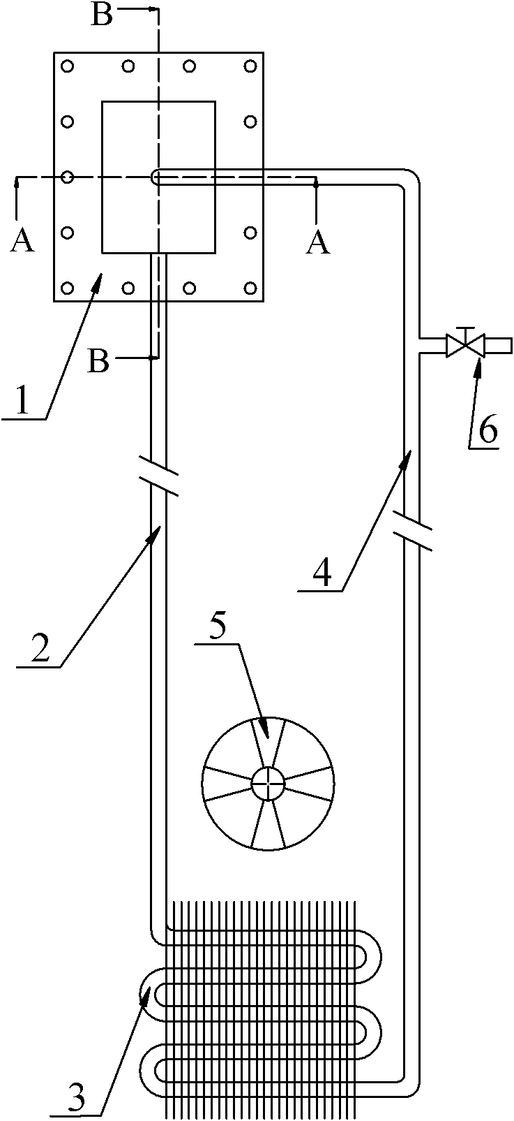
[0020] like Figure 1 to Figure 3 As shown, the flat-plate loop heat pipe of the present invention includes an evaporator 1 and a condenser 3 . The working medium outlet of the evaporator 1 is connected with the working medium inlet of the condenser 3 through the steam pipeline 2, and the working medium outlet of the condenser 3 is connected with the working medium inlet of the evaporator 1 through the liquid pipeline 4, thereby forming an "evaporator 1—steam pipeline 2—condenser 3—liquid pipeline 4—evaporator 1” working fluid circulation system. In addition, a working fluid filling port 6 is also provided on the liquid pipeline 4 . in:

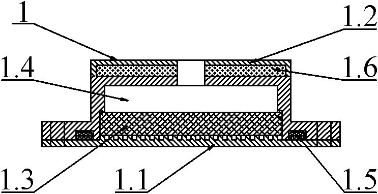
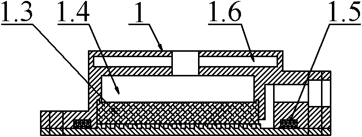
[0021] The evaporator 1 includes a flat heating wall surface 1.1, a shell 1.2 and a capillary core 1.3. The heating wall surface 1.1 is provided with heat conducti...


PUM


Abstract

The invention discloses a flat type loop heat pipe, relates to the radiation of components and is used for solving the problem of dead start resulted from liquid working medium phase change in a liquid compensation cavity of an evaporimeter of the existing loop heat pipe. The flat type loop heat pipe comprises the evaporimeter and a condenser, the working medium outlet of the evaporimeter is communicated with the working medium inlet of the condenser through a steam line, and the working medium outlet of the condenser is communicated with the working medium inlet of the evaporimeter. The evaporimeter comprises a flat type heated wall surface and a shell, wherein the heated wall surface is provided with porous wicks; the shell covers the porous wicks and is provided with the liquid compensation cavity above the porous wicks; the liquid compensation cavity is used for containing working medium and is connected with the liquid line through the working medium inlet; and the wall of the shell is internally provided with a phase-change material layer. Through the phase-change material layer arranged inside the wall of the shell, the invention absorbs back leakage heat and heat conducted by a lateral wall of the evaporimeter through the phase-change heat absorption of the phase change material, thereby effectively inhibiting the generation of bubbles in the liquid compensation cavity and ensuring the smoothly starting of the loop heat pipe.

Description

technical field [0001] The invention relates to heat dissipation of components, in particular to a flat-plate loop heat pipe. Background technique [0002] The loop heat pipe is a loop system that relies on capillary suction to drive the circulation of the working fluid and uses the phase change of the working fluid to transfer heat. It is a split heat pipe developed from an ordinary heat pipe. Compared with ordinary heat pipes, the difference of the loop heat pipe is that its capillary structure only exists in the evaporator, and the evaporator and condenser are separated. In this way, the steam pipeline and the liquid pipeline can be arranged arbitrarily, so the loop heat pipe has a wider range of applications. In addition, the loop heat pipe has the advantages of strong heat transfer capacity, good isothermal performance, long transmission distance and high safety factor, and is an ideal heat dissipation device. [0003] Furthermore, it is more reasonable to use a flat-...

Claims


Application Information

Patent Timeline
Patent Type & Authority Applications(China)
IPC IPC(8): F28D15/04
Inventor 盖东兴龙妍邵远敬
Owner WISDRI ENG & RES INC LTD
Why Eureka
Try Eureka