Liquid crystal display panel and preparation method thereof

A liquid crystal display panel and liquid crystal technology, applied in nonlinear optics, instruments, optics, etc., can solve problems such as gravity water ripples of liquid crystal display panels, affecting the display quality of liquid crystal display panels, etc., to reduce high-temperature gravity water ripples and low-temperature air bubbles, Improve the display effect and reduce the effect of bad phenomena

Inactive Publication Date: 2010-12-01
BOE TECH GRP CO LTD +1
View PDF0 Cites 33 Cited by
  • Summary
  • Abstract
  • Description
  • Claims
  • Application Information

AI Technical Summary

Problems solved by technology

[0004] However, in the process of carrying out the research of the present invention, the inventors found that existing liquid crystal display panels that maintain cell thickness by setting PS have certain defects: the liquid crystal display panel manufactured at room temperature, when in a high temperature environment, the volume of liquid crystal It will increase due to thermal expansion. The liquid crystal display panel is placed vertically when it is used, so the liquid crystal display panel will have the undesirable phenomenon of gravitational water ripples (mura); when it is in a low temperature environment, the volume of the liquid crystal will decrease due to shrinkage. There is a gap between them, so the liquid crystal display panel will have a bad phenomenon of low-temperature bubbles (bubble)
PS is generally made of polymethyl methacrylate (Polymethyl Methacrylate; hereinafter referred to as: PMMA) or polycarbonate (hereinafter referred to as: PC) and other resins, because the material of PS is difficult to match the coefficient of thermal expansion of liquid crystal (Coefficient of Thermal Expansion ; hereinafter referred to as: CTE) remains consistent, so the above-mentioned high-temperature gravity water ripples and low-temperature air bubbles are unavoidable, which seriously affects the display quality of the LCD panel

Method used


Image

  • Liquid crystal display panel and preparation method thereof
  • Liquid crystal display panel and preparation method thereof
  • Liquid crystal display panel and preparation method thereof

Examples


no. 1 example

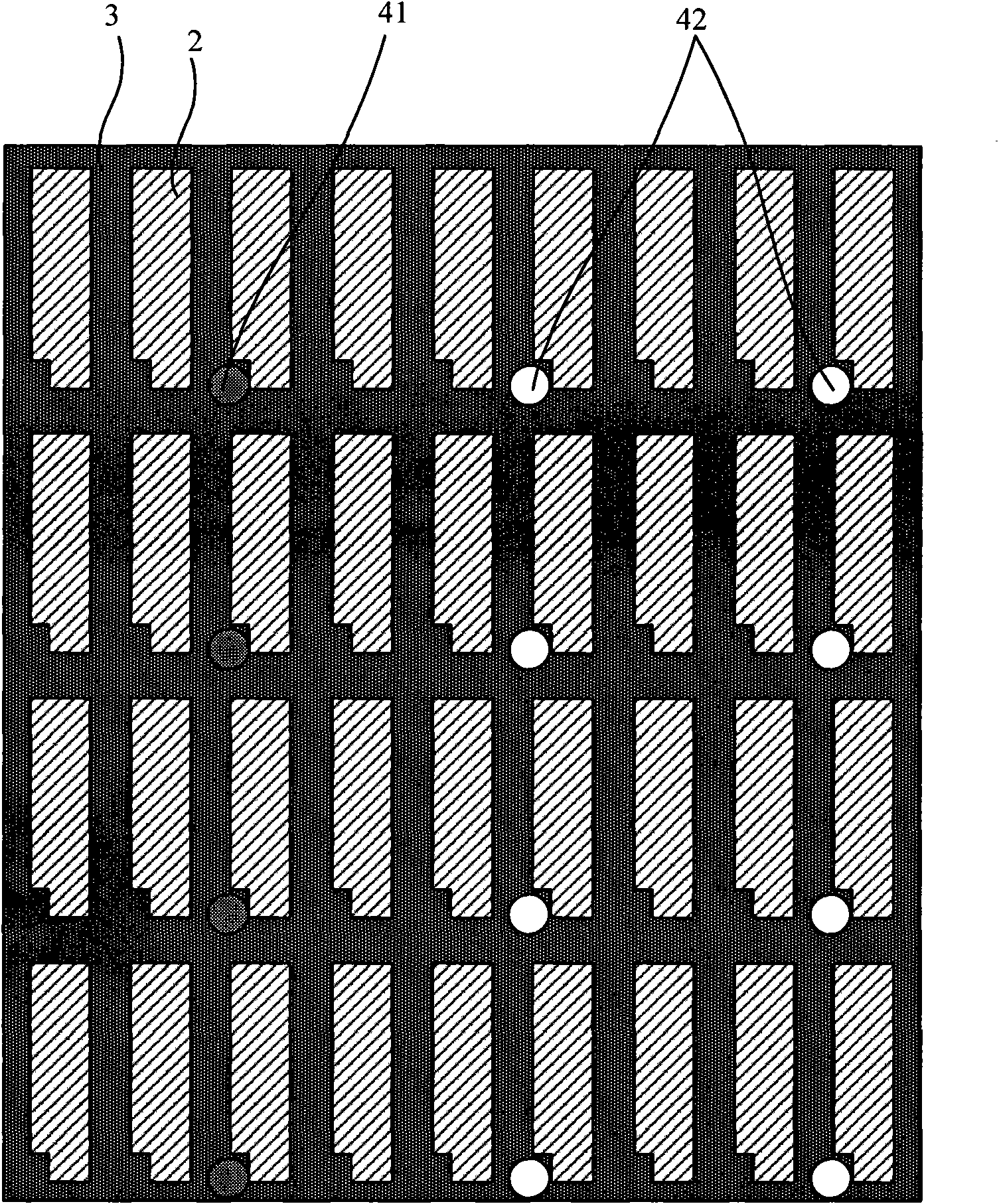
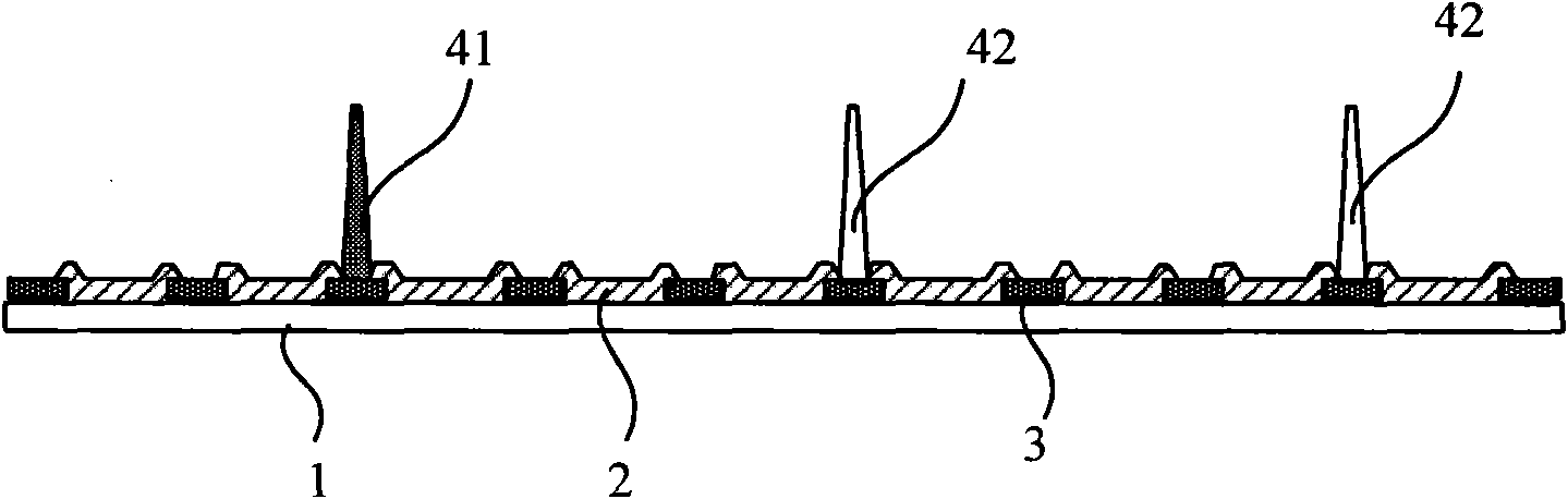
[0031] figure 1 It is a partial top view structure schematic diagram of a substrate in the liquid crystal display panel provided by the first embodiment of the present invention, figure 2 for figure 1 The schematic diagram of the side view structure, the spacer is arranged between the first substrate and the second substrate, figure 1 and 2 Shown is the case where the spacers are formed on one substrate, and specifically the color filter substrate. Such as figure 1Shown is a top view of some pixel units on the color filter substrate. The color filter substrate usually includes a first base substrate 1 made of glass and other materials, and a color filter resin 2 and a black matrix 3 are arranged on the first base substrate 1 . Each resin block corresponds to a sub-pixel unit, and every three color filter resins 2 correspond to a pixel unit. The black matrix 3 corresponds to areas on the array substrate that need to be shielded from light, such as data scan lines, gate sc...

no. 2 example

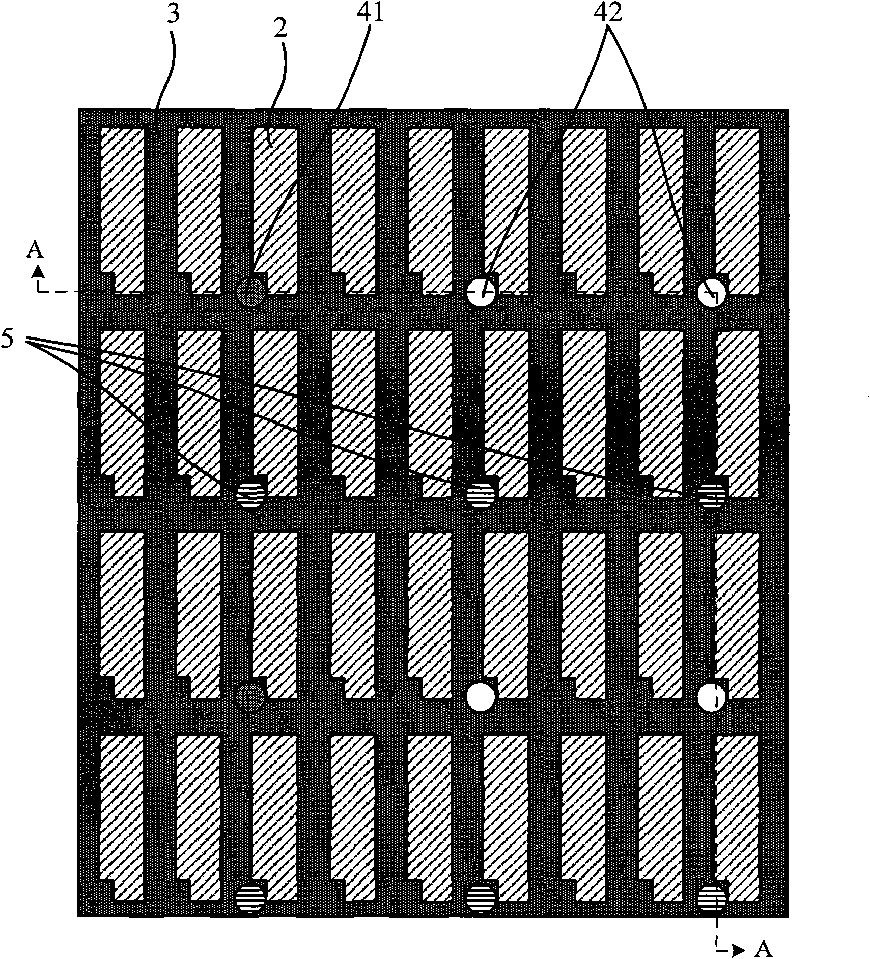
[0037] image 3 It is a partial top view structural schematic diagram of a substrate in a liquid crystal display panel provided by the second embodiment of the present invention, Figure 4 for image 3 The schematic diagram of the cross-sectional structure along the A-A line, the difference between this embodiment and the first embodiment is that the spacer in the above-mentioned first embodiment is the main spacer, and in this embodiment, the main spacer is placed between the two The distribution density between the substrates is lowered, and sub-spacers 5 are formed between the first and second substrates in addition to the first and second spacers 41 and 42 as main spacers. The sub-spacer 5 can also be arranged on the black matrix 3 of the color filter substrate, and when the liquid crystal is in a normal state, the height of the sub-spacer 5 is smaller than that of the main spacer. The so-called normal state of the liquid crystal refers to the state that the liquid cryst...

no. 3 example

[0041] Figure 5 It is a partial top view structure schematic diagram of a substrate in a liquid crystal display panel provided by the third embodiment of the present invention, Figure 6 for Figure 5 The difference between this embodiment and the above-mentioned first embodiment is that the spacer is made of three materials, that is, the third spacer 43 is also included, and the thermal expansion of the material used for the third spacer 43 The coefficient may be greater than, equal to, or less than the coefficient of thermal expansion of the liquid crystal. When the first spacer 41, the second spacer 42 and the third spacer 43 are present at the same time, the spacers of various materials are arranged at intervals, and it is preferable that the number ratio thereof satisfies the overall thermal expansion of the spacers The coefficient is approximately equal to the thermal expansion coefficient of the liquid crystal.

[0042] The specific number ratio can be calculated, a...


PUM


Abstract

The invention relates to a liquid crystal display panel and a preparation method thereof. The liquid crystal display panel comprises a first substrate and a second substrate, wherein a plurality of spacers are formed between the first substrate and the second substrate; the spacers at least comprise a first spacer and a second spacer; the thermal expansion coefficient of the material adopted by the first spacer is less than the thermal expansion coefficient of liquid crystal; the thermal expansion coefficient of the material adopted by the second spacer is greater than the thermal expansion coefficient of the liquid crystal; and the first spacer and the second spacer are arranged in a spacing mode. The preparation method comprises the following steps: respectively preparing and forming the first spacer and the second spacer on one or two substrates, and folding the two substrates to form the liquid crystal display panel. In the invention, by the combined actions of the spacers of different materials, the integral thermal expansion coefficient of the spacers is approximate to the thermal expansion coefficient of the liquid crystal, thereby enhancing the capacity of the spacers in keeping the box thickness, reducing the adverse phenomena of high-temperature gravity water ripple and low-temperature air bubbles appearing on the liquid crystal display panel, and improving the display effect.

Description

technical field [0001] The invention relates to liquid crystal display structure technology, in particular to a liquid crystal display panel and a preparation method thereof. Background technique [0002] The liquid crystal display panel includes a first substrate and a second substrate, and is formed by injecting liquid crystal between the two substrates. The two substrates of a common liquid crystal display panel are an array substrate and a color filter substrate. In the manufacturing process of the liquid crystal display panel, the thickness of the liquid crystal layer is a very important control factor, and the thickness of the liquid crystal layer can be controlled by controlling the distance between the two substrates, that is, the cell thickness (Cell Gap). [0003] In order to keep the thickness of the cell between the first substrate and the second substrate consistent at each position in the plane of the entire liquid crystal display panel, the prior art mainly a...

Claims


Application Information

Patent Timeline
Patent Type & Authority Applications(China)
IPC IPC(8): G02F1/1339G02F1/1333
CPCG02F1/13394G02F1/133512G02F2001/13396G02F2001/13398G02F1/13396G02F1/13398
Inventor 赵海玉
Owner BOE TECH GRP CO LTD
Why Eureka
Try Eureka