
Detection method and system of zero mark exposure

A detection method and zero-marking technology, which is applied in microlithography exposure equipment, photo-plate-making process exposure devices, etc., can solve the lack of ZeroMark exposure detection and other problems, and achieve the effect of high effectiveness and efficiency

Inactive Publication Date: 2010-12-01
SEMICON MFG INT (SHANGHAI) CORP
View PDF0 Cites 4 Cited by
  • Summary
  • Abstract
  • Description
  • Claims
  • Application Information

AI Technical Summary

Problems solved by technology

[0004] After exposure processing, although the accuracy of the Zero Mark mark position or area will generally be improved, whether the improved accuracy meets the requirements after exposure, that is, whether the exposure is qualified and achieves the expected effect, usually needs to be tested, but there is currently a lack of Zero Mark exposure detection scheme

Method used


Image

  • Detection method and system of zero mark exposure
  • Detection method and system of zero mark exposure
  • Detection method and system of zero mark exposure

Examples


Embodiment Construction

[0013] Although the invention will be described in more detail below with reference to the accompanying drawings, in which preferred embodiments of the invention are shown, it should be understood that those skilled in the art can modify the invention described herein and still achieve the advantageous effects of the invention. Therefore, the following description should be understood as the broad knowledge of those skilled in the art, but not as a limitation of the present invention.

[0014] In the interest of clarity, not all features of an actual implementation are described. In the following description, well-known functions and constructions are not described in detail since they would obscure the invention with unnecessary detail. It should be appreciated that in the development of any actual embodiment, numerous implementation details must be worked out to achieve the developer's specific goals, such as changing from one embodiment to another in accordance with system-...


PUM


Abstract

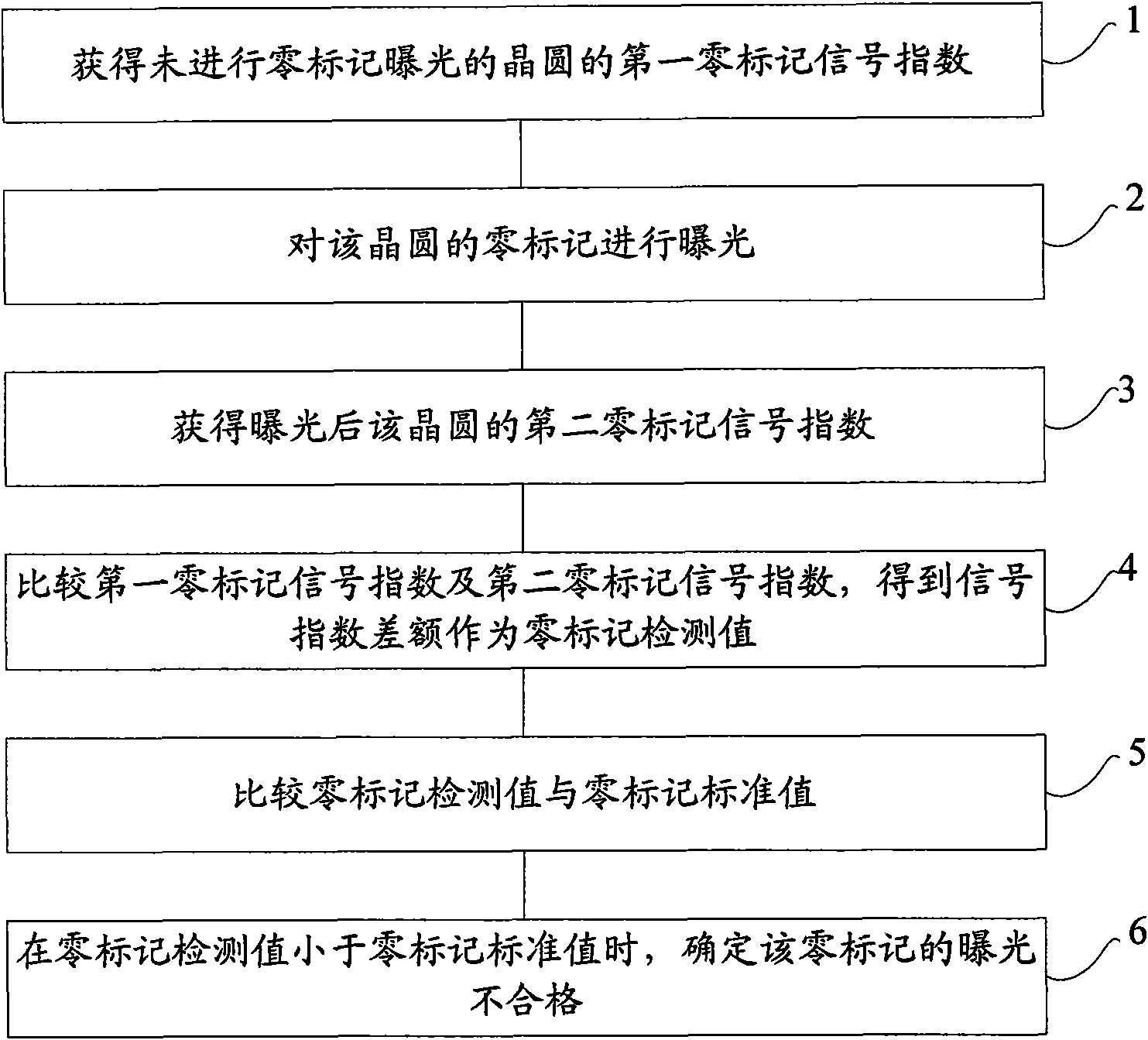
The invention provides detection method and system of zero mark exposure so as to realize the zero mark exposure detection. The method comprises the following steps of: acquiring a first zero mark signal index of a wafer in which the zero mark exposure is not carried out; carrying out exposure on a zero mark of the wafer; acquiring a second zero mark signal index of the exposed wafer; comparing the first zero mark signal index with the second zero mark signal index to obtain a signal index difference as a zero mark detection value; and comparing the zero mark detection value with a zero mark standard value, and when the zero mark detection value is less than the zero mark standard value, determining that the exposure of the zero mark is not qualified.

Description

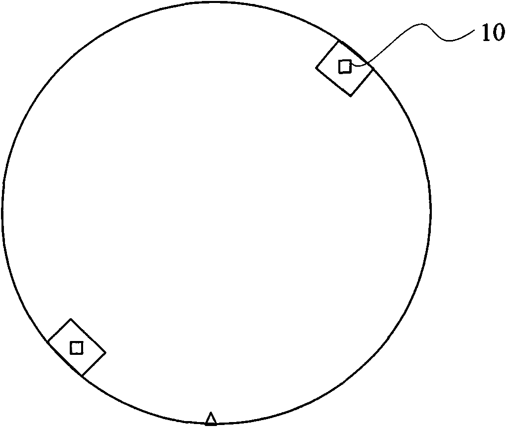
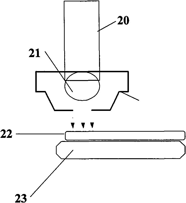
technical field [0001] The invention relates to the field of semiconductor manufacturing, in particular to a detection method and system for zero-mark exposure. Background technique [0002] When manufacturing semiconductor products, it is necessary to process multiple layers of wafers. In order to ensure that the position of each layer of the semiconductor product matches, when each layer is processed, the position of the process is usually determined based on the Zero Mark. Refer to figure 1 , which is a schematic diagram of the position of the Zero Mark on the wafer. Since ZeroMark may make its position or area inaccurate due to its upper layer or edge substance coverage, thereby reducing the marking effect of ZeroMark, it is generally used in the wafer edge exposure (WEE, Wafer Edge Exposure) equipment in the glue developing machine (Track) Expose the Zero Mark to improve the accuracy of the Zero Mark position or area. [0003] figure 2 It is a schematic diagram of ...

Claims


Application Information

Patent Timeline
Patent Type & Authority Applications(China)
IPC IPC(8): G03F7/20
Inventor 袁文勋邹渊渊梁国亮
Owner SEMICON MFG INT (SHANGHAI) CORP
Learn More