Deposited manganese sheet automatic detachment machine on electrolytic manganese metal negative plate

An electrolytic manganese metal, automatic detachment technology, applied in the electrolysis process, electrolysis components, etc., can solve the problems of easy breakage of the hammer rod, large error, complex structure, etc., and achieve the effect of flexible tapping action

Inactive Publication Date: 2010-12-08
HUNAN HONGYANG TECH
View PDF3 Cites 15 Cited by
  • Summary
  • Abstract
  • Description
  • Claims
  • Application Information

AI Technical Summary

Problems solved by technology

But the disadvantage is that there are still the following disadvantages: (1) The operation is not stable enough: during use, when the automatic plate separation device transports the cathode plates to the chain, mistakes often occur, and the plates cannot be normally divided, and the error is relatively large; (2) The hammer rod has a short service life: the applicant found that the hammer rod is easy to break during use; (3) not environmentally friendly: there is no smoke absorption and treatment device, the working environment is harsh, and it is harmful to human health; (4) the control is not flexible: timing The control transmission device cannot be flexibly adjusted according to actual needs, so that it cannot meet the needs of various working conditions; (5) The structure is complex: when striking, the vibratory hammer and the plate baffle act simultaneously, and the vibratory hammer moves through The cam mechanism is realized, and the action of the plate stopper is realized by a thrust electromagnet and a set of elastic brackets. The structure is relatively complicated and the production cost is high.

Method used


Image

  • Deposited manganese sheet automatic detachment machine on electrolytic manganese metal negative plate
  • Deposited manganese sheet automatic detachment machine on electrolytic manganese metal negative plate
  • Deposited manganese sheet automatic detachment machine on electrolytic manganese metal negative plate

Examples


Embodiment Construction

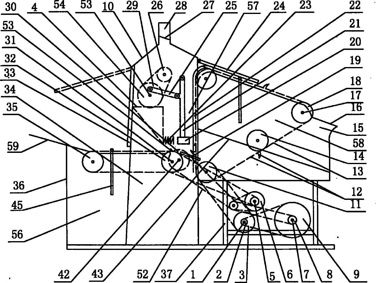
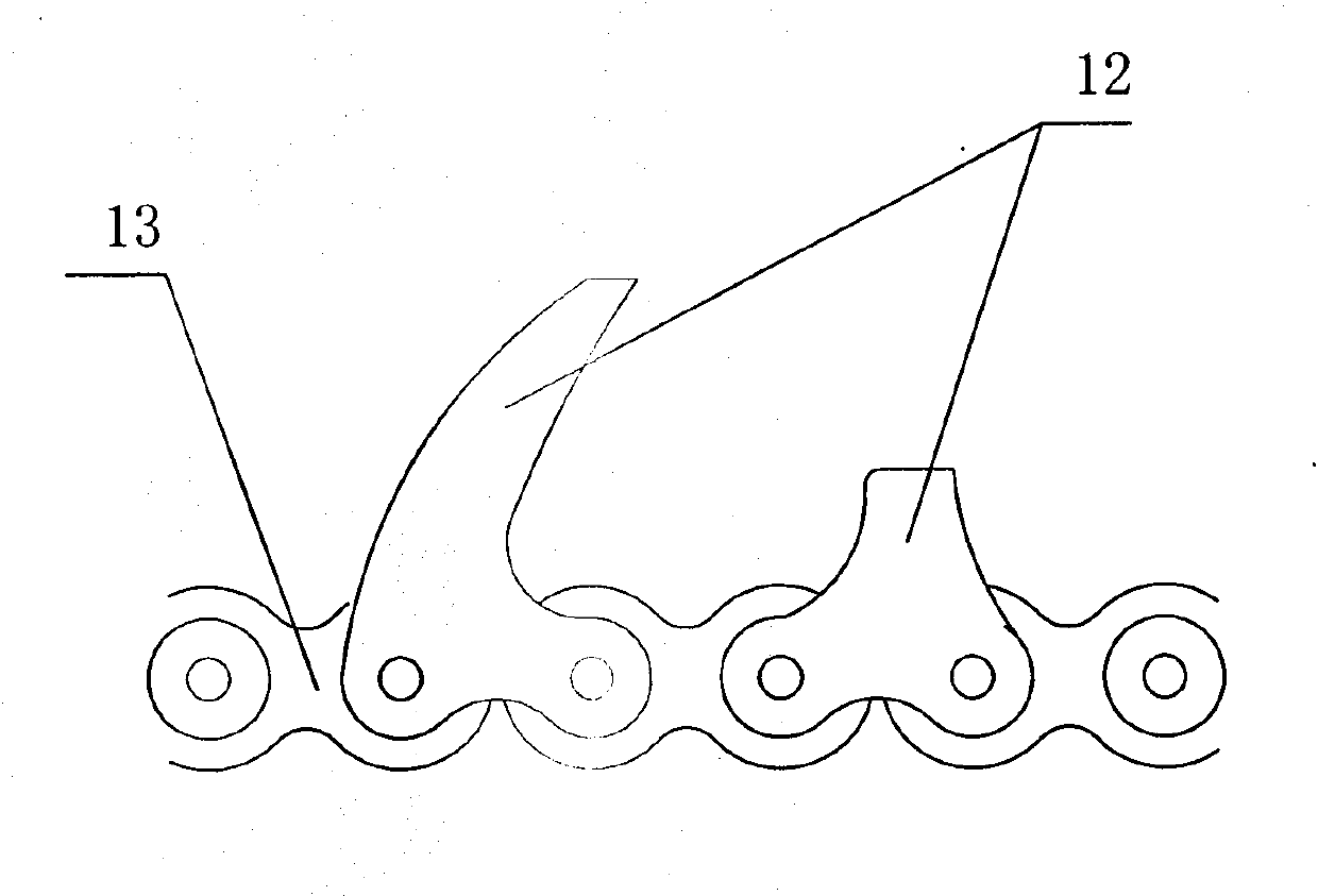
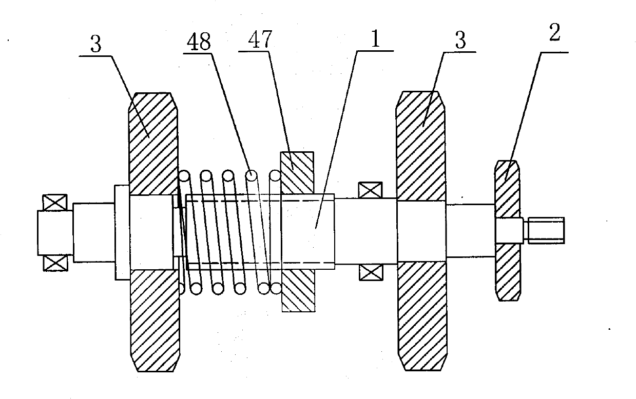
[0027] Such as Figure 1-Figure 3 As shown, the front portion of the main frame 37 is provided with a plate-feeding support 36 , the top is provided with a plate-feeding support 16 , and the top of the plate-feeding support 36 is provided with a knocking plate support 4 . Both sides of the board-feeding support 36 are symmetrically provided with a board-feeding vertical plate 40, and a plate-feeding sprocket shaft 31 is installed on the plate-feeding vertical plate 40, and a plate-feeding driving sprocket 32, a plate-feeding driven sprocket 35 and a plate-feeding plate are installed The chain 39 constitutes a plate-feeding mechanism, which is used to continuously transport the pole plate 45 to the plate-separating wheel 30 , and a plate-feeding channel 56 is formed between the two plate-feeding vertical plates 40 . The both sides of the lose plate support 16 are symmetrically provided with the lose plate vertical plate 15, the lose plate vertical plate 15 is equipped with the ...


PUM

PropertyMeasurementUnit
diameteraaaaaaaaaa

Abstract

The invention discloses an electrolytic manganese metal automatic detachment machine, which is provided with a plate feeding channel and a plate conveying channel, wherein a vertical plate lifting channel is formed between the plate feeding channel and the plate conveying channel; a knock rapping device is arranged above the plate feeding channel; plate conveying upright plates on two sides of the plate conveying channel are provided with plate conveying chains which are provided with polar plate hook groups; and a main frame below the plate conveying channel is provided with a transmission main shaft, an infrared sensing timing control driving device and a plate feeding and plate conveying driving device. The knock rapping device comprises an eccentric wheel, a tappet and a driving hammer; a kick spring is arranged in front of the driving hammer; a guide rail and a polar plate supporting block are arranged in the plate lifting channel; and a plate dividing wheel and a polar plate receiving and feeding block are arranged between the plate feeding channel and the plate lifting channel. The detachment machine has the advantages of long service life, steady running, environmental protection, flexible control, simple structure, convenient operation, does not damage a plate, has a plate correcting function, and can greatly reduce the production cost of manganese metal and improve the production efficiency.

Description

technical field [0001] The invention relates to smelting machinery, in particular to an automatic detachment machine for deposited manganese flakes on the electrolytic metal manganese cathode plate. Background technique [0002] At present, the electrolytic smelting industry of metal manganese is rapidly emerging and developing, but the smelting and purification industry does not have any automatic detachment machinery for electrodeposited metal on the cathode plate, and all detachment is done manually or semi-manually. Manual detachment is labor-intensive, the working environment is poor, and the efficiency is low, which seriously endangers the health of workers, and it is also very easy to damage the cathode plate. The damage of the cathode plate affects the output on the one hand, and it is easy to damage the anode bag on the other hand. Resulting in high production costs in the industry. [0003] The applicant applied for a utility model patent on June 25, 2009, the pat...

Claims


Application Information

Patent Timeline
Patent Type & Authority Applications(China)
IPC IPC(8): C25C7/08
Inventor 陈天贵高红旺刘正权孟祥顺段继元白峰
Owner HUNAN HONGYANG TECH
Why Eureka
Try Eureka