Gas purifying process and gas purifying apparatus

a gas purification apparatus and gas purification technology, applied in the direction of combustible gas purification/modification, separation processes, physical/chemical process catalysts, etc., can solve the problems variable expense and fixed expense of apparatuses or heat exchangers, and unable to separate carbon monoxide from nitrogen by distillation, etc., to achieve efficient removal of hydrogen and carbon monoxide, prevent the effect of increasing the power consumed for heating

Inactive Publication Date: 2000-04-11
NIPPON SANSO CORP
View PDF7 Cites 104 Cited by
  • Summary
  • Abstract
  • Description
  • Claims
  • Application Information

AI Technical Summary

Benefits of technology

It is an objective of the present invention to provide a process and an apparatus for purifying a gas, which can prevent increase in the power consumed for heating, variable expense

Problems solved by technology

However, all of such impurities as described above cannot be separated from nitrogen by distillation according to the cryogenic separation process, but water and carbon dioxide are in many cases removed by means of adsorption in the raw air supply system.
Further, carbon monoxide and nitrogen have approximately the same boiling points, so that it is difficult to separate carbon monoxide from nitrogen by means of distillation.
While this method is successful in improving efficiency of the apparatus by utilization of the heat of compression, heat recovery by heat exchangers, etc., it inevitably leads to increase in the power consumed for heating, variable expense and fixed expense for apparatuses or heat exchanger, etc.
However, to pack a catalyst between a desiccant and a CO.sub

Method used


Image

  • Gas purifying process and gas purifying apparatus
  • Gas purifying process and gas purifying apparatus
  • Gas purifying process and gas purifying apparatus

Examples


Embodiment Construction

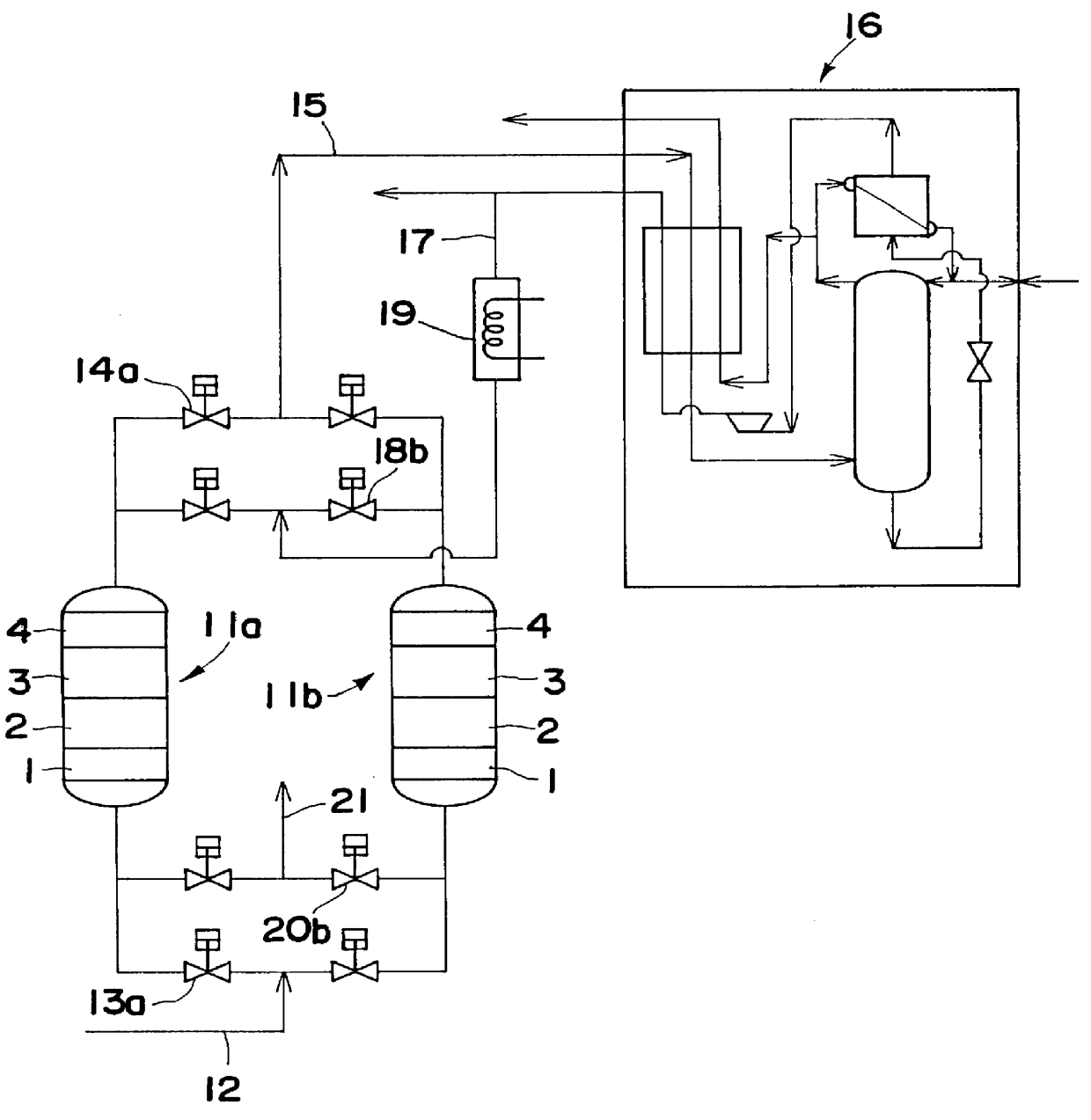
Raw air containing impurities to be removed in the amounts as described below was introduced to a packed column 11 of a purifying apparatus shown in FIG. 4 to carry out purification.

Raw air:

pressure: 600 kPA

temperature: 10.degree. C.; saturated with moisture

Impurities: CO 5 ppm, H.sub.2 10 ppm, CO.sub.2 400 ppm

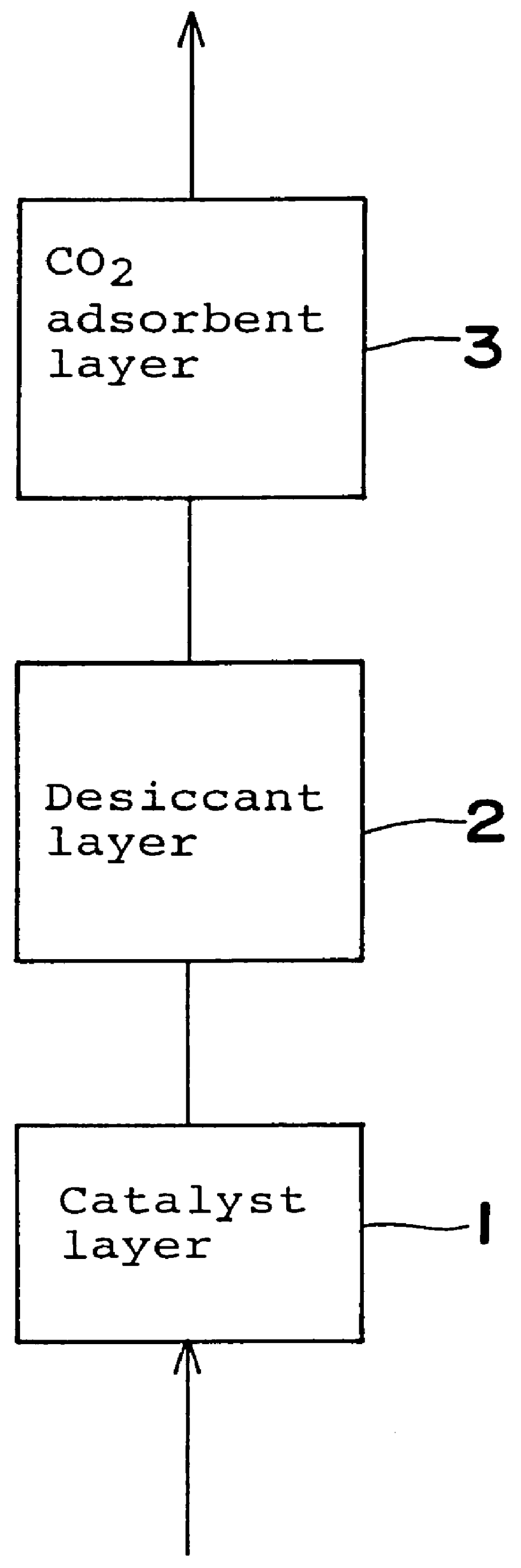
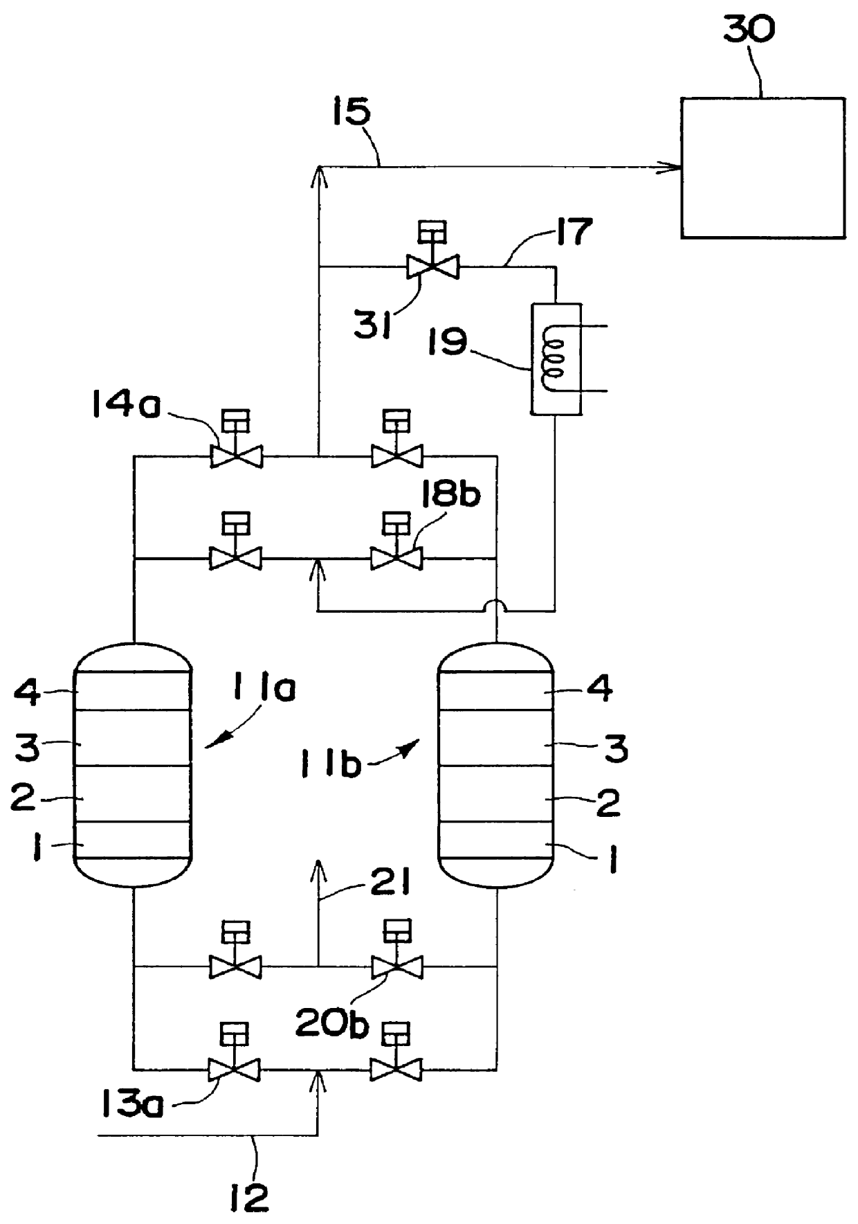
Catalyst layer 1: Platinum and iron-on-alumina catalyst (3 g & 1.4 g / 100 ml)

Desiccant layer 2: Activated alumina

CO.sub.2 adsorbent layer 3: Synthetic zeolite Na-X type Hydrogen removing layer 4: Palladium-on-zeolite catalyst (0.3 g / 100 ml)

The raw air was supplied at a fixed flow rate, and dew point, carbon dioxide, hydrogen and carbon monoxide were determined. An optical hygrometer, an infrared gas analyzer and a reduction detector were employed respectively for the determination. The results of determination are shown in FIG. 5.

As shown in FIG. 5, no carbon monoxide was detected over the entire period of determination. The hydrogen concentration increased gradually with break...


PUM

PropertyMeasurementUnit
Pore sizeaaaaaaaaaa
Percent by massaaaaaaaaaa
Temperatureaaaaaaaaaa

Abstract

A method is provided for removing water, carbon monoxide and carbon dioxide out of a gas, such as air, by passing the gas through a packed column so that the gas sequentially contacts a catalyst consisting of platinum or palladium and at least one member selected from the group consisting of iron, cobalt, nickel, manganese, copper, chromium, tin, lead and cerium wherein the catalyst is supported on alumina containing substantially no pores having pore diameters of 110 Angstroms or less under conditions which oxidize the carbon monoxide in the gas into carbon dioxide; an adsorbent selected from the group consisting of silica gel, activated alumina, zeolite and combinations thereof under conditions in which water is adsorbed and removed from the gas and an adsorbent selected from the group consisting of calcium ion exchanged A zeolite; calcium ion exchanged X zeolite; sodium ion exchanged X zeolite and mixtures thereof under conditions which carbon dioxide is adsorbed and removed from the gas. The gas may also be subjected to a catalyst/adsorbent in the packed column to effect oxidation and removal of hydrogen in the gas.

Description

BACKGROUND OF THE INVENTION AND RELATED ART STATEMENTThe present invention relates to a process and an apparatus for purifying a gas, particularly to a process and an apparatus for purifying a gas containing as major components oxygen and nitrogen and as impurities to be removed at least water, carbon dioxide and carbon monoxide. More specifically, the present invention relates to a process and an apparatus for purifying raw air so as to supply the treated air as clean dry air. The present invention also relates to a process and an apparatus for purifying a gas which are suitably realized in a pre-treating equipment for purifying a raw air to be supplied to a cryogenic separation unit by carrying out oxidation of trace hydrogen and trace carbon monoxide contained in the raw air to form water and carbon dioxide and remove them using adsorbents, respectively.Recently, there is an increasing demand for high-purity gases, and particularly nitrogen gas, which is consumed in large amounts...

Claims


Application Information

Patent Timeline
IPC IPC(8): B01D53/04B01D53/86B01D53/26B01J23/56B01J23/89
CPCB01D53/0423B01D53/261B01D53/864B01D53/04B01D2253/104B01D2253/106Y02C10/08B01D2253/308B01D2257/504B01D2257/80B01D2259/4009B01D2259/4146B01D2253/108Y02C20/40B01D53/263
Inventor KAWAI, MASATONAKAMURA, MORIMITSUOKAMURA, NOBUHIRO
Owner NIPPON SANSO CORP
Why Eureka
Try Eureka