

Screed vibrator and paver
A screed and vibrator technology, applied in the field of construction machinery, can solve problems such as troublesome construction process, affect the surrounding environment, affect the construction environment, etc., and achieve the effects of saving adjustment time, reducing work difficulty, and improving working environment.
- Summary
- Abstract
- Description
- Claims
- Application Information
AI Technical Summary
Problems solved by technology
Method used
Image

Examples
Embodiment Construction
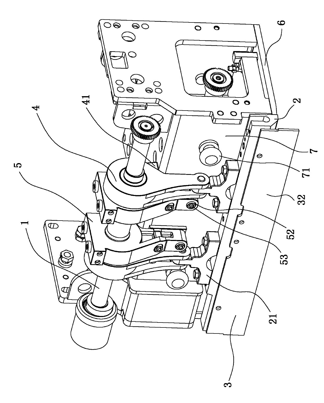
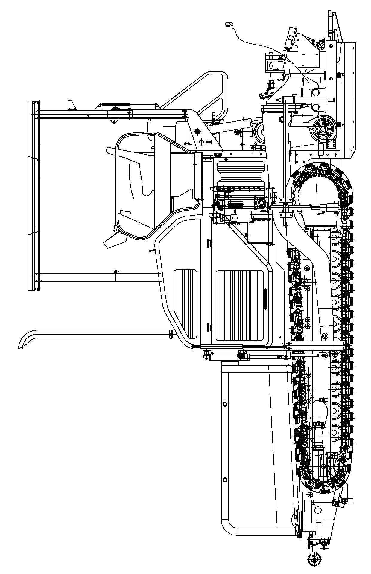
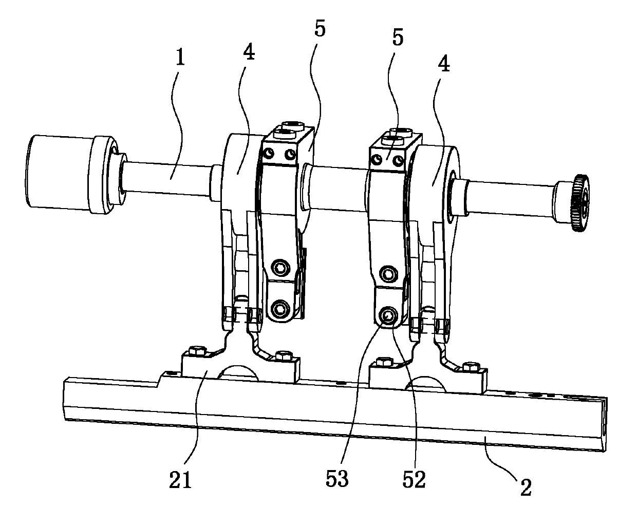
[0023] Figure 1 to Figure 5 A screed vibrator of the present invention is shown, including an eccentric shaft 1, a blade 2, a vibrating connection seat 4, a vibrating support seat 5 and a fixed guard plate 3, and the vibrating support seat 5 is installed on the screed 9 On the plate frame 7, the eccentric shaft 1 is horizontally arranged in front of the plate frame 7, and is supported on the vibrating support seat 5. The upper end of the vibrating connecting seat 4 is in the shape of a cylinder, and is provided with an eccentric mounting hole suitable for the eccentric shaft 1. , the lower end of the vibrating connecting seat 4 extends tangentially downward from the cylinder at the upper end to form two left and right walls, which are connected by reinforcing ribs, the ends of the left and right walls are round, and hinged holes are arranged in the circular area The upper end of the vibrating connecting seat 4 is installed on the eccentric shaft 1 through the eccentric mounti...
PUM
 Abstract
Description
Claims
Application Information