Method and water chutes for adjusting water-wet distribution of water-storage type evaporative cooling wall

An evaporative cooling and water guiding technology, applied in the field of water guiding channels, can solve the problem that a porous water storage body cannot fully absorb moisture, etc., and achieve the effect of simple structure and ingenious conception.

Inactive Publication Date: 2010-12-08
何玉成
View PDF5 Cites 11 Cited by
  • Summary
  • Abstract
  • Description
  • Claims
  • Application Information

AI Technical Summary

Problems solved by technology

Because the outer wall of the water storage evaporative cooling wall is unavoidably blocked by doors, windows or concave-convex shapes, the water flowing from top to bottom along the joints of the facing brick layers of the water storage evaporative cooling wall cannot flow to the windows Underneath or some concave-convex structures, the porous water storage body on this part cannot fully absorb moisture

Method used


Image

  • Method and water chutes for adjusting water-wet distribution of water-storage type evaporative cooling wall
  • Method and water chutes for adjusting water-wet distribution of water-storage type evaporative cooling wall
  • Method and water chutes for adjusting water-wet distribution of water-storage type evaporative cooling wall

Examples


Embodiment 1

[0032] Example 1: see Figure 1 to Figure 9 , the present invention is a kind of method for regulating the water-humidity distribution of water-storage evaporation cooling wall body, and it comprises the following steps:

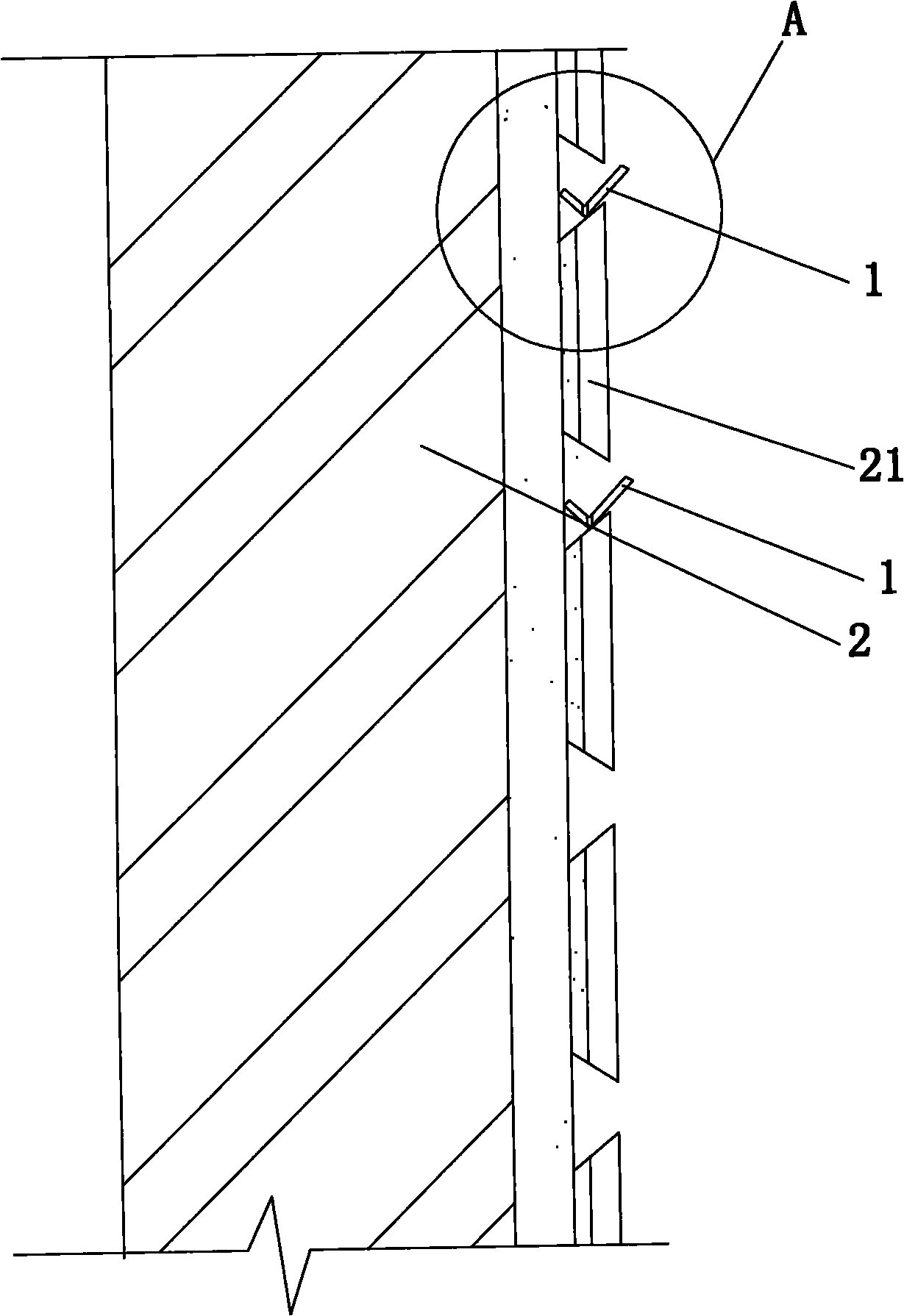
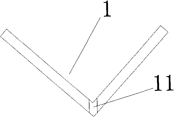
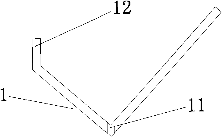
[0033] (1) Prepare some aqueducts 1, the section of which is unequal L-shaped, U-shaped or unequal trapezoid, the opening of the aqueduct 1 is wide and the bottom is narrow, and the bottom of the aqueduct 1 is intercepted from above A number of water outlet holes 11 are required to flow downward or guide the water flow from top to bottom;

[0034] (2) Place the opening of the water guiding channel 1 facing upwards in the horizontal joint of the decorative brick layer 21 of the water storage evaporation cooling wall 2 that needs to adjust the water humidity distribution;

[0035] (3) When the water flows from top to bottom, since one side of the water guide groove 1 is closely attached to the water storage evaporation cooling wall 2, the water flow is collec...

Embodiment 2

[0046] Example 2, see Figure 2 to Figure 10, this embodiment is mostly the same as Embodiment 1, the difference is that the opening of the water guiding groove 1 faces upwards, and it is stuck on the multi-level decorative brick layer 21 of the water storage evaporation cooling wall 2 that needs to adjust the water and humidity distribution. A multi-stage water guide groove 1 is formed in the seam, and the multi-stage transverse joints are arranged horizontally and distributed in parallel intervals; One side of the water tank 1 is closely attached to the water storage evaporative cooling wall 2, so the water flows through the surface of the facing brick layer 21 and then collects in the water guide channel 1 arranged in the lower transverse joint; A water outlet hole 11 is required for water flow or guiding water flow, so the water flow flows out from the set water outlet hole 11 again, flows through the surface of the facing brick layer 21 arranged at the lower part of the t...


PUM


Abstract

The invention discloses a method for adjusting the water-wet distribution of a water-storage type evaporative cooling wall, which comprises the following steps that: 1) preparing a plurality of water chutes, wherein the water chute has a wide opening and a narrow bottom, and a plurality of water outlets are formed at the bottom of the water chute in a way of intercepting a water flow form top down or guiding a water flow from top down according to the requirements; 2) clamping the water chutes (with openings upwards) in transverse seams of a decorative brick layer of a water-storage type evaporative cooling wall of which the water-wet distribution is required to be adjusted; 3) when the water flow runs from top down, because one edge of each water chute is arranged against the evaporativecooling wall, the water flow is collected to the water chute; 4) because the bottom of the water chute is provided with the water outlets according to the requirement for intercepting or guiding the water flow, draining the water flow out from the water outlets to adjust the water-wet distribution of the water-storage type evaporative cooling wall. The method and the water chutes of the inventionare simple in structure and clever in design, and can make porous water-storage bodies arranged below windows of the water-storage type evaporative cooling wall or on some concave-convex structures of the water-storage type evaporative cooling wall absorb moisture sufficiently, and are of benefit to energy conservation and environmental protection.

Description

technical field [0001] The invention relates to the technical fields of energy saving, emission reduction and construction engineering, in particular to a method for adjusting water and humidity distribution of water storage, evaporation and cooling walls, and a water guiding channel for implementing the method. Background technique [0002] In the prior art, water storage, evaporative cooling and energy saving of buildings requires regular input of water source to the porous water storage body of the water storage evaporative cooling wall, and the water source introduced into the porous water storage body in the water storage evaporative cooling wall is mainly It flows from top to bottom, so that the porous water storage body can fully absorb moisture. Because the outer wall of the water storage evaporative cooling wall is unavoidably blocked by doors, windows or concave-convex shapes, the water flowing from top to bottom along the joints of the facing brick layers of the w...

Claims


Application Information

Patent Timeline
Patent Type & Authority Applications(China)
IPC IPC(8): E04B1/74E04B2/00
Inventor 何玉成
Owner 何玉成
Why Eureka
Try Eureka