

Vacuum insulation panels and refrigerators
A technology of vacuum thermal insulation panels and thermal insulation boxes, which is applied to heat exchange equipment, lighting and heating equipment, and protection pipes through thermal insulation, etc.
- Summary
- Abstract
- Description
- Claims
- Application Information
AI Technical Summary
Problems solved by technology
Method used
Image

Examples
no. 1 approach
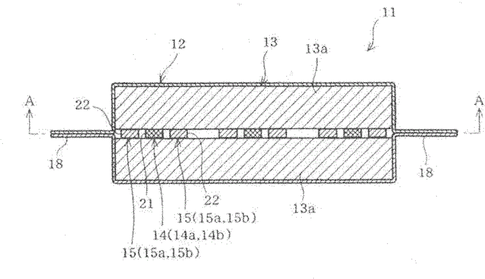
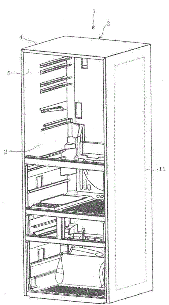
[0035] First of all, figure 2 The illustrated refrigerator main body 1 is configured such that a refrigeration cycle (not shown) and the like are installed in a heat-insulating box 2 having a longitudinally long rectangular box shape with an opening on the front surface.
[0036] In addition, detailed description is omitted, but the inside of the heat-insulating box 2 is partitioned up and down (and partly left and right), and a plurality of storage rooms 3 such as a refrigerator compartment, a vegetable compartment, and a freezer compartment are provided. On the front surface of each storage room 3, a hinged opening and closing type thermal insulation or a pull-out thermal insulation is provided.
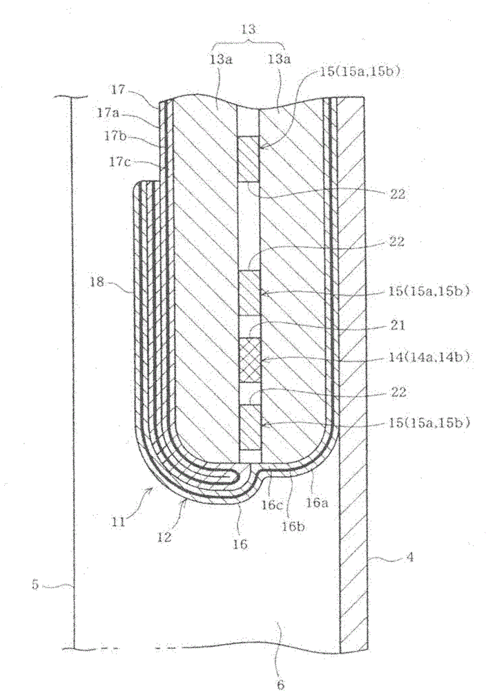
[0037] The heat-insulating box 2 has an outer box 4 made of steel plate, an inner box 5 made of synthetic resin housed in the outer box 4, and a vacuum insulation panel 11 provided between the outer box 4 and the inner box 5.
[0038] In addition, such as image 3 As shown, the heat-insu...
no. 2 example
[0092] Figure 7 The vacuum insulation panel 31 of the second embodiment of the present invention is shown. In addition, the same reference numerals are given to the same parts as the above-mentioned first embodiment, and detailed descriptions thereof are omitted.
[0093] In the second embodiment, such as Figure 7 As shown, the arrangement of the first air-permeable bag 21 containing the first moisture absorbent 14 and the second air-permeable bag 22 containing the second moisture absorbent 15 is different from the above-mentioned first embodiment.
[0094] That is, in the vacuum insulation panel 31 of the second embodiment, the first air-permeable bag 21 containing the first moisture absorbent 14 is arranged at the corner of the core material 13 (laminated body 13a), and the second moisture absorbent 15 is contained therein. The second air-permeable bag 22 is arranged in four directions with the first air-permeable bag 21 as the center.
[0095] Figure 7 The illustrated core mat...
no. 3 approach
[0100] Picture 8 The vacuum insulation panel 41 of the third embodiment of the present invention is shown. In addition, the same reference numerals are given to the same parts as the above-mentioned first embodiment, and detailed descriptions thereof are omitted.
[0101] The first hygroscopic agent 14 and the second hygroscopic agent 15 of the vacuum insulation panel 41 are not contained in the first air-permeable bag 21 and the second air-permeable bag 22 shown in the first embodiment, but are evenly dispersed Between the laminated bodies 13a of the core material 13.
[0102] The magnesium oxide 14a and the anhydrous magnesium chloride 14b of the first moisture absorbent 14 in the vacuum insulation panel 41 are in the form of particles, respectively. The maximum length of the particles of magnesium oxide 14a and anhydrous magnesium chloride 14b is preferably 0.5 to 3 mm.
[0103] In addition, in the case of using calcium oxide 15a as the second moisture absorbent 15, the calcium...
PUM
 Abstract
Description
Claims
Application Information