Laser POS computer system structure

A computer system and computer technology, applied in the fields of navigation, guidance and control, can solve the problems of inconvenient maintenance or replacement of internal devices and components, and the volume, volume, and weight of high-precision POS, so as to improve the working temperature environment and improve Work stability, effect of size and weight reduction

Inactive Publication Date: 2012-05-23
BEIHANG UNIV
View PDF0 Cites 0 Cited by
  • Summary
  • Abstract
  • Description
  • Claims
  • Application Information

AI Technical Summary

Problems solved by technology

The most typical POS computer system is the POS / AV510 and POS / AV610 POS computer systems developed by Canada APPLANIX Company. In addition, the American Z / I Imaging Company has also developed a miniaturized POS computer system (POS Z / I) for optical loads, but the above The computer system for POS is not easy to disassemble, and it is not convenient for repair or replacement of internal devices and components
Another POS computer system is the computer system for AeroControl Position and Attitude System (POS) developed by German IGI Company.

Method used


Image

  • Laser POS computer system structure
  • Laser POS computer system structure
  • Laser POS computer system structure

Examples


Embodiment Construction

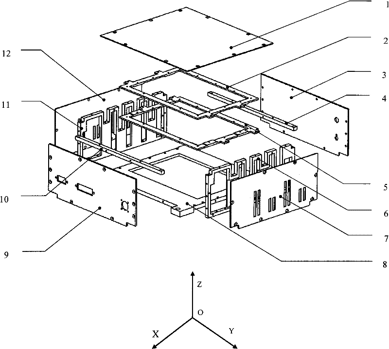
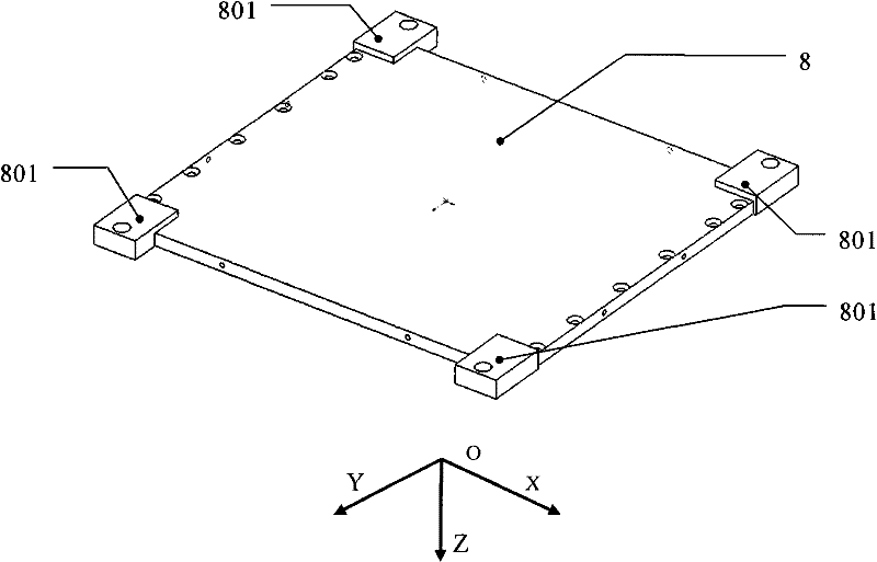
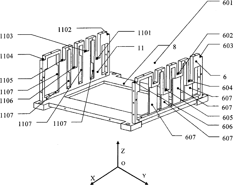
[0023] The specific implementation structure of the present invention is as figure 1 As shown, the laser POS computer system structure consists of base 8, left side bracket 11, left side panel 12, right side bracket 6, right side panel 7, computer bracket 5, expansion board bracket 2, front panel 3, rear panel 9, front Crossbeam 4, rear crossbeam 10 and loam cake 1 form. The left side bracket 11 is installed on the left side of the upper surface of the base 8, the right side bracket 6 is installed on the right side of the upper surface of the base 8, and the computer bracket 5 is installed on the left side bracket 11 and the lower "U" groove of the right side bracket 6; the expansion board bracket 2 Installed to the upper "U" groove of the left bracket 11 and the right bracket 6; the front panel 3 and the rear panel 9 are installed on the left side bracket 11, the right bracket 6 and the front and rear sides of the base 8; the front beam 4 and the rear beam 1O Installed to th...


PUM


Abstract

The invention discloses a laser POS computer system structure, which comprises a base, a left bracket, a left panel, a right bracket, a right panel, a computer bracket, an expansion board bracket, a front panel, a rear panel, a front cross beam, a rear cross beam and an upper cover. The left bracket and the right bracket are arranged on the left and the right of the upper surface of the base respectively, and the computer bracket is arranged in a lower U-shaped groove of the left bracket and the right bracket; the expansion board bracket is arranged in an upper U-shaped groove of the left bracket and the right bracket; the front panel and the rear panel are arranged on the front and rear lateral surfaces of the base, the left bracket and the right bracket respectively; the front cross beam and the rear cross beam are arranged in grooves of the left bracket and the right bracket respectively; the left panel and the right panel are arranged on the outer surfaces of the left bracket and the right bracket respectively; and the upper cover is arranged on the upper surfaces of the left bracket and the right bracket. The laser POS computer system structure reduces the volume and mass andis suitable for a computer system of inertial navigation, combined navigation and the like.

Description

technical field [0001] The invention belongs to the technical field of navigation, guidance and control, and relates to a laser POS (Position and Orientation System, position and attitude measurement system) computer system structure, which can be applied to the laser POS system, and can also be applied to inertial navigation, inertial / GPS (Global Position System, Global Positioning System) integrated navigation system. Background technique [0002] The aerial remote sensing system has unique advantages in many aspects such as mobility, real-time performance, repeatable observation, replaceability of remote sensing equipment, ability to obtain high-resolution remote sensing data, economic cost, and stereoscopic observation. For high-resolution aerial remote sensing systems, in addition to high-resolution remote sensing payloads, the main factor restricting the imaging resolution of remote sensing systems is high-precision POS. High-precision POS provides high-precision posi...

Claims


Application Information

Patent Timeline
Patent Type & Authority Patents(China)
IPC IPC(8): G06F1/18G01C21/20
Inventor 李建利房建成钟麦英刘百奇康泰钟闫东坤
Owner BEIHANG UNIV
Why Eureka
Try Eureka