Ultrasonic flow measuring device

A flow measuring device, ultrasonic technology, applied in measuring devices, measuring flow/mass flow, liquid/fluid solid measurement, etc., can solve problems such as easy blockage, achieve small changes in fluid flow paths, improve measurement accuracy, and reduce pressure loss small effect

Inactive Publication Date: 2010-12-08
李俊国 +2
View PDF7 Cites 14 Cited by
  • Summary
  • Abstract
  • Description
  • Claims
  • Application Information

AI Technical Summary

Problems solved by technology

[0013] The purpose of the present invention is to overcome the technical problem that the existing U-shaped ultrasonic flow measurement device is prone to blockage in the case o

Method used


Image

  • Ultrasonic flow measuring device
  • Ultrasonic flow measuring device
  • Ultrasonic flow measuring device

Examples


Embodiment

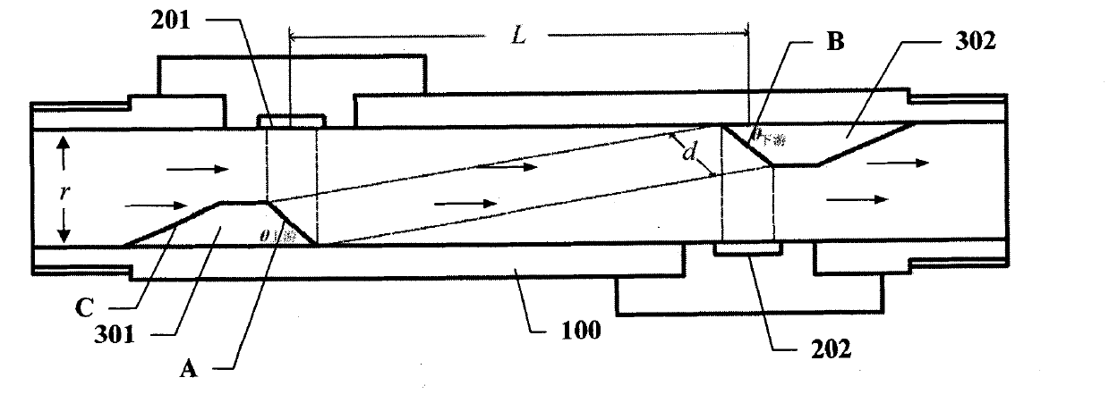
[0036] In this example, if figure 2 As shown, the ultrasonic flow measurement device includes a fluid pipeline 100 and upstream and downstream ultrasonic transducers 201 , 202 installed opposite to each other perpendicular to the pipe wall at a certain distance L on the inner pipe wall of the fluid pipe 100 . At the same time, a reflection block 301, 302 is installed directly opposite the upstream and downstream ultrasonic transducers 201, 202 in the fluid pipeline 100, and the reflection surface A of the upstream reflection block 301 forms an included angle θ of 35-43 degrees with the fluid inflow direction. 上游 , the angle θ between the reflection surface B of the downstream reflection block 302 and the fluid outflow direction is 35-45 degrees 下游 .

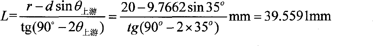
[0037] The spacing L approximately satisfies:

[0038]

[0039] Wherein, r is the inner diameter of the fluid pipe, and d is the length of the reflection surface of the reflection block.

[0040] like figure 2 As shown, wh...

example 1

[0043] In this example, if image 3 As shown, the inner diameter r of the fluid pipeline 100 is 20mm, and the included angle θ 下游 = Angle θ 上游 =40°, the projected length of reflective surfaces A and B on the fluid pipeline 100 is 8 mm, that is, the length d of the centerline of the reflective surface of the reflective block along the direction of fluid flow is:

[0044] d=8mm / cos40°=10.4433mm

[0045] The spacing L approximately satisfies:

[0046]

[0047] In this implementation, we can see that the reflective surfaces A and B increase the effective distance L of ultrasonic propagation to 75.3555mm, thereby improving the measurement accuracy.

[0048] In this implementation, if Figure 4 As shown, since the reflective block 301 is placed on the pipe wall, the distance from its center to the opposite pipe wall is 13.2872mm. It can be seen that the fluid flow area is relatively large, so that the ultrasonic flow measuring device of the present invention is not easy to de...

example 2

[0050] like Figure 5 As shown, in this implementation, except for the included angle θ 下游 = Angle θ 上游 =43°, other parameters are exactly the same as Example 1.

[0051] The length d of the center line of the reflective surface of the reflective block along the fluid flow direction is:

[0052] d=8mm / cos43°=10.9386mm

[0053] The spacing L approximately satisfies:

[0054]

[0055] Compared with Example 1, the included angle θ 上游 An increase of 3 degrees, but the spacing L increased by 103.9731mm, so if the angle θ 上游 After the angle is greater than 43 degrees, the processing accuracy requirements for the installation positions of the upstream and downstream ultrasonic transducers 201 and 202 and the upstream and downstream reflection blocks 301 and 302 are very high, so the included angle θ 上游 Less than or equal to 43 degrees.

[0056] In this implementation, if Image 6 As shown, the distance from the center of the reflection block 301 to the opposite pipe wall i...


PUM


Abstract

The invention discloses an ultrasonic flow measuring device, which comprises a fluid tube and upstream and downstream ultrasonic transducers which are arranged on an inner tube wall of the fluid tube at a certain interval L and oppositely arranged in a way of being vertical to the tube wall, wherein a reflection block is arranged in front of each ultrasonic transducer; the reflection surface of the upstream reflection block is at an upstream included angle theta of 35 to 43 degrees to the inflow direction of fluid, the reflection surface of the downstream reflection block is at a downstream included angle theta of 35 to 43 degrees to the outflow direction of the fluid, and the upstream included angle theta is equal to the downstream included angle theta; the interval L is approximately equal to (r-dsin upstream theta)/tg(90DEG-2downstream theta); and in the formula, r is the inner diameter of the fluid tube, and d is the central line length of the reflection surface of the reflection block in the flowing direction of the fluid. In the ultrasonic flow measuring device, the reflection surface of the reflection block is an inclined surface of 35 to 43 degrees, and the reflection surface of the reflection block prolongs the effective distance L of the transmission of ultrasonic waves, so that measuring precision is improved. Meanwhile, both the reflection block and the ultrasonic transducers are arranged on the tube wall and the flow area of the fluid is large, so that the ultrasonic flow measuring device of the invention is difficult to block in sites with impurities. Thus, the ultrasonic flow measuring device is particularly suitable for measuring the flow of the fluid which flows slowly in a small-diameter tube.

Description

technical field [0001] The invention belongs to the technical field of ultrasonic measurement, and relates to an ultrasonic flow measurement device. Background technique [0002] When the ultrasonic wave propagates in the flowing fluid, it carries the information of the fluid flow velocity, so the flow velocity of the fluid can be detected through the received ultrasonic wave, and then converted into flow rate to complete the test of the fluid flow rate. According to the detection method, it can be divided into different types of ultrasonic flowmeters such as propagation velocity difference method, Doppler method, beam shift method, noise method and correlation method. [0003] When ultrasonic waves are used to measure fluid flow velocity, the velocity and direction of the fluid in the flow path will cause signal differences in the propagation of ultrasonic signals in the fluid. This difference depends on the objective physical laws of fluid flow velocity and ultrasonic prop...

Claims


Application Information

Patent Timeline
IPC IPC(8): G01F1/66
Inventor 李俊国蔡波廖斌
Owner 李俊国
Why Eureka
Try Eureka