Inspection fixture and inspection probe

A fixture and contact technology, applied in the field of inspection fixtures, can solve the problems of impracticality, difficult assembly of inspection fixtures, extremely difficult formation of coiled coil springs, etc., and achieves the effect of ensuring elasticity and easy plating

Active Publication Date: 2010-12-08
NIDEC-READ CORPORATION
View PDF5 Cites 18 Cited by
  • Summary
  • Abstract
  • Description
  • Claims
  • Application Information

AI Technical Summary

Problems solved by technology

[0012] However, in the inspection jig disclosed in Patent Document 1, since it is formed by a coil spring using a wound wire, it is difficult to form a coil having a diameter about four times smaller than the diameter of the wound wire, and it is extremely difficult to form a coil

Method used


Image

  • Inspection fixture and inspection probe
  • Inspection fixture and inspection probe
  • Inspection fixture and inspection probe

Examples


Embodiment Construction

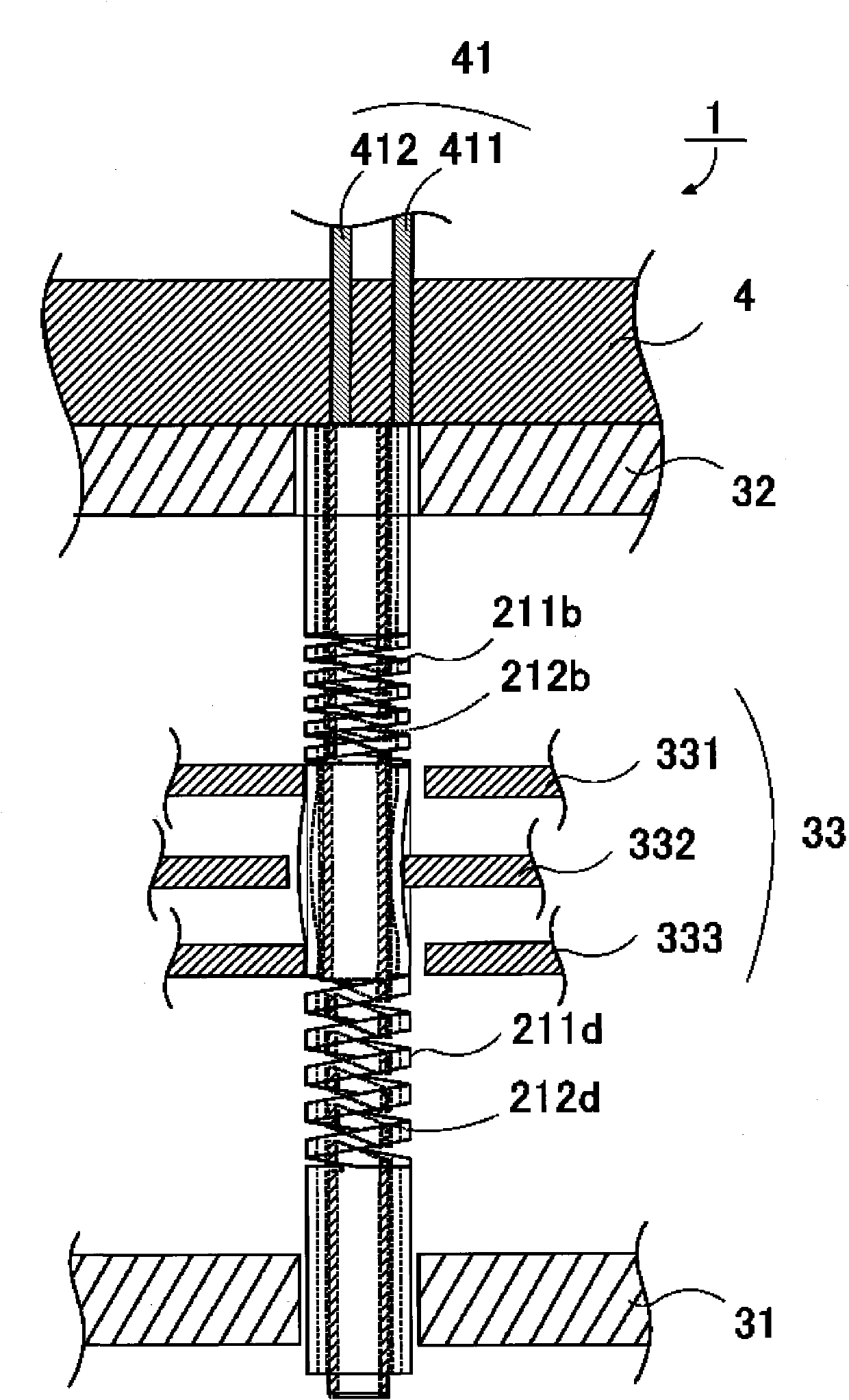
[0052] Modes for implementing the present invention will be described. figure 1 It is a schematic configuration diagram showing an embodiment of the inspection jig according to the present invention. The inspection jig 1 according to the present invention has a plurality of contacts 2, a holding body 3 holding these contacts 2 in a multi-needle shape, and an electrode that supports the holding body 3 and contacts the contacts 2 to be in a conductive state. Section 41 (see Figure 5 ) connected to the electrode body 4, and the lead portion 5 provided to extend from the electrode portion 41 and electrically connected thereto.

[0053] also, figure 1 Although three contacts are shown as a plurality of contacts 2 and three corresponding lead parts 5 are shown in the figure, they can be determined according to the inspection points set by the substrate of the inspection object, and are not limited to three. root.

[0054] The main feature of the present invention is that two co...


PUM


Abstract

The invention provides an inspection fixture and inspection probe. The inspection fixture has probe for four terminal measuring, capable of coping substrate small size and complication and having simplification structure with reduced component number. The inspection fixture for electric connection of the object to be inspected and the inspection device, has: an electrode part electrically connected to the inspection device; a conductive barrel shaped first barrel, one end of whose is in pressure welding to the inspection part and the other end is in pressure welding to the electrode part; anda conductive barrel shaped second barrel, roughly coaxially configured in the first barrel, wherein one end of the second barrel is in pressure welding to the inspection part and the other end is in pressure welding to the electrode part, two expansion parts formed on the spiral incision part of the barrel wall part in the long axis direction are provided on the first barrel and the second barrelpartitioned with intermediate parts, and the first barrel and the second barrel are fixed on their own intermediate parts.

Description

technical field [0001] The present invention relates to an inspection jig that electrically connects an inspection point set in advance on an inspection object portion of an object to be inspected to an inspection device that performs the inspection, and particularly relates to an inspection contact that can easily perform four-terminal measurement and its use. The contact inspection jig. Background technique [0002] The inspection jig of the present invention can detect the electrical characteristics of the inspection object by supplying electric power or electrical signals to a predetermined inspection position from the inspection device to the inspection object part of the inspection object and detecting the electrical signal from the inspection object part. , or perform an action test. [0003] The objects to be inspected in the present invention include, for example, various substrates such as printed wiring boards, flexible substrates, ceramic multilayer wiring board...

Claims


Application Information

Patent Timeline
IPC IPC(8): G01R1/04G01R1/067
CPCG01R1/06722G01R1/06755G01R1/073G01R3/00G01R31/28
Inventor 春日部进沼田清
Owner NIDEC-READ CORPORATION
Why Eureka
Try Eureka