Processing technology of ultra-high-brightness ceramic substrate used for LED

A technology of ceramic substrate and processing technology, which is applied in the field of ceramic substrate processing technology for ultra-high-brightness LEDs. It can solve the problems of insufficient grinding and repair, insufficient flatness and smoothness of the cut surface, and inconvenient coating of ceramic substrates with metal layers. To achieve the effect of preventing debris from splashing, high fit and complete angle

Active Publication Date: 2019-08-30
浙江蔚蓝航盾精密陶瓷科技有限公司
View PDF7 Cites 0 Cited by
  • Summary
  • Abstract
  • Description
  • Claims
  • Application Information

AI Technical Summary

Problems solved by technology

[0004] The purpose of the present invention is to solve the problem that the existing ceramic substrates for ultra-high-brightness LEDs have a slow cutting efficiency when being processed, and after the ceramic substrates are cut and divided, the cut surfaces of the ceramic substrates are not enough. Flat and smooth, resulting in a poor fit of the ceramic substrate for use with LED lights in the later stage, and when the ceramic substrate is processed, the grinding and trimming is not comprehensive and thorough, and it is not convenient to plate a metal layer on the ceramic substrate in the later stage, and the existing The overall implementation efficiency of the ceramic substrate processing technology is very slow, and the implementation is time-consuming and laborious. The ceramic substrate processing technology for ultra-high brightness LEDs is proposed

Method used

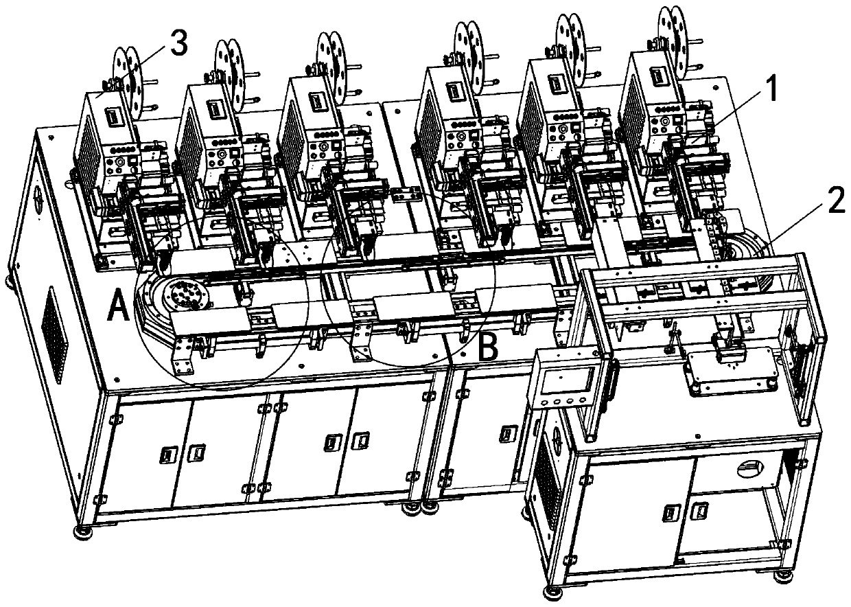
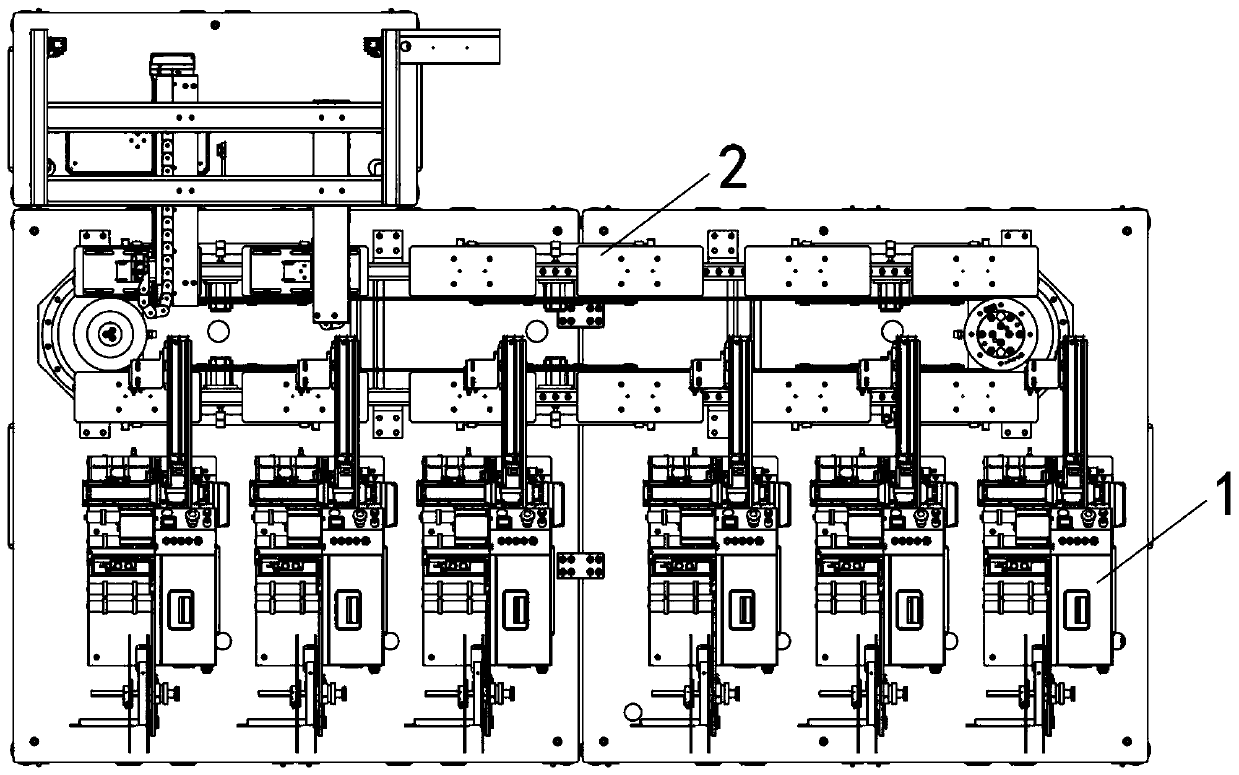
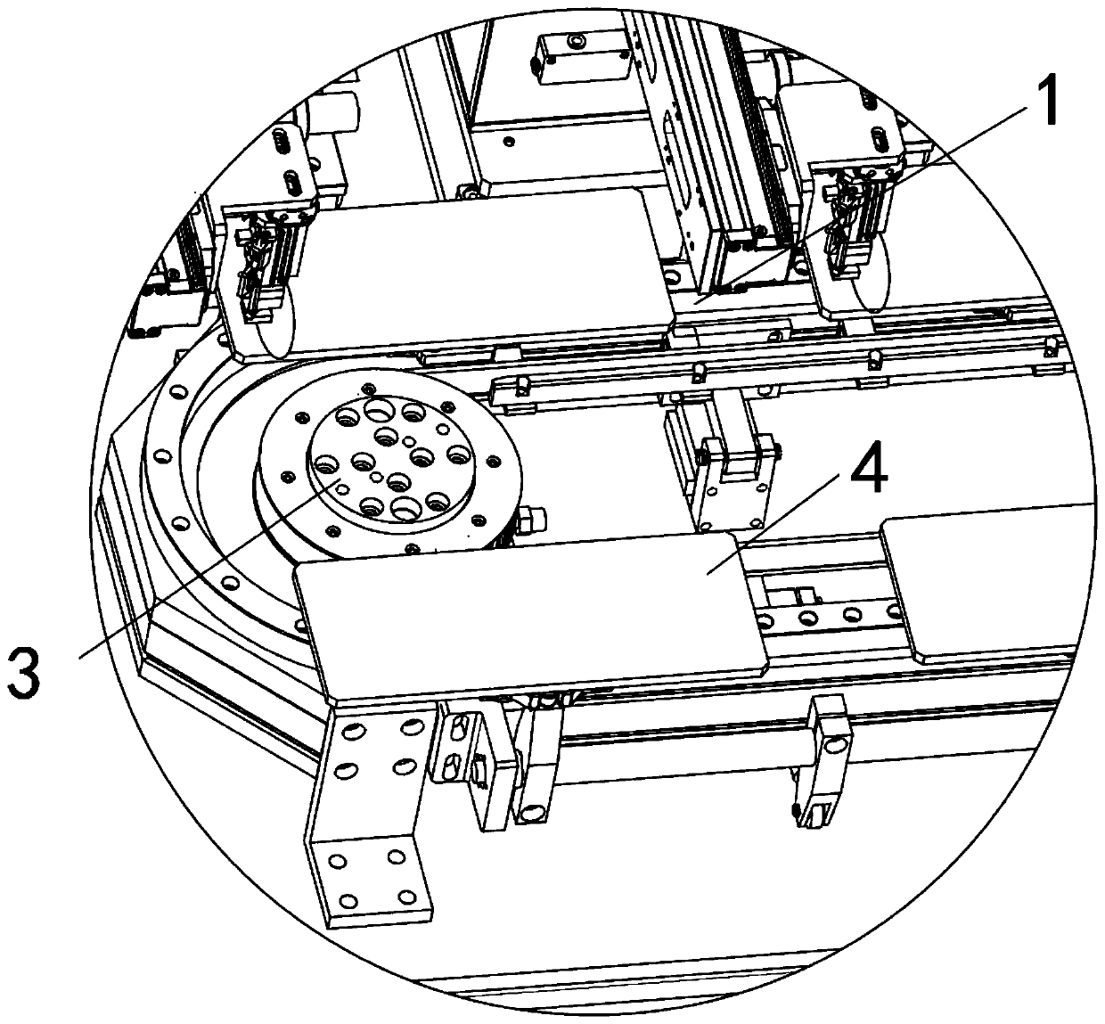

Image

  • Processing technology of ultra-high-brightness ceramic substrate used for LED
  • Processing technology of ultra-high-brightness ceramic substrate used for LED
  • Processing technology of ultra-high-brightness ceramic substrate used for LED

Examples


Embodiment Construction

[0048] The following will clearly and completely describe the technical solutions in the embodiments of the present invention with reference to the accompanying drawings in the embodiments of the present invention. Obviously, the described embodiments are only some, not all, embodiments of the present invention. Based on the embodiments of the present invention, all other embodiments obtained by persons of ordinary skill in the art without creative efforts fall within the protection scope of the present invention.

[0049] A traditional process of melt spinning, comprising preparation of sintering aid-preparation of ceramic slurry-ceramic stamper-ceramic sintering-substrate cutting-substrate surface modification-substrate surface metallization process steps, the specific steps are as follows:

[0050] Step 1: Preparation of sintering aid: disperse calcium oxide, silicon powder, aluminum powder, bauxite, and kaolin powder into absolute ethanol to form a mixed slurry, and dry to ...


PUM


Abstract

The invention discloses a processing technology of an ultra-high-brightness ceramic substrate used for an LED. The process comprises the following steps: preparing a sintering aid, preparing ceramic slurry, performing ceramic stamping, performing ceramic sintering, performing substrate cutting, performing substrate surface finishing, and performing substrate surface metallization, wherein the sintering aid is prepared by the following steps: dispersing calcium oxide, silicon powder, aluminum powder, bauxite and kaolin powder into anhydrous ethanol to form mixed slurry, and performing drying toobtain the sintering aid. According to the process provided by the invention, when a cutting device adopted in the process is adopted to cut the sintered ceramic substrate, a motor 2 drives the ceramic substrate on a wobble plate to rotate to adjust positions, so that a cutting position of the ceramic substrate is ensured to be more precise and suitable by rotation of cut blades on a cutting table; and a motor 3 moves front and back in a groove of an upper slide rail, thereby driving the cut blades to move front and back to adjust positions, ensuring that positions of the cutting blades on the ceramic substrate are more accurate, and ensuring that the cut surface of the ceramic substrate is flatter and more round after the cutting device cuts the ceramic substrate.

Description

technical field [0001] The invention relates to the technical field of ceramic substrates, in particular to a processing technology of ceramic substrates for ultra-high brightness LEDs. Background technique [0002] Ceramic substrate refers to a special process board in which copper foil is directly bonded to the surface of an alumina or aluminum nitride ceramic substrate at high temperature. The produced ultra-thin composite substrate has excellent electrical insulation performance, high thermal conductivity, excellent solderability and high adhesion strength, and can etch various patterns like a PCB board, and has a large current-carrying capacity. ability. Ceramic substrates are increasingly used in ultra-high brightness LED lamps. [0003] The existing ceramic substrates for ultra-high-brightness LEDs still have many deficiencies when they are processed. Moreover, after the ceramic substrate is cut into pieces, the cut surface of the ceramic substrate is not flat and ...

Claims


Application Information

Patent Timeline
Patent Type & Authority Applications(China)
IPC IPC(8): C04B35/10C04B35/64C04B35/636C04B35/622C04B41/88F21V23/00F21Y115/10
CPCC04B35/10C04B35/64C04B35/6365C04B35/622C04B41/009C04B41/51C04B41/88F21V23/004F21Y2115/10C04B2235/428
Inventor 不公告发明人
Owner 浙江蔚蓝航盾精密陶瓷科技有限公司
Why Eureka
Try Eureka