Supercharge Your Innovation With Domain-Expert AI Agents!

High-frequency structure and centering method for gyrotron amplifier

A high-frequency structure and amplifier technology, applied in the microwave field, can solve problems such as not being able to meet high average power, and achieve the effects of overcoming the inability to use high average power, improving stability, and improving output power and efficiency

Active Publication Date: 2012-07-04
INST OF ELECTRONICS CHINESE ACAD OF SCI
View PDF0 Cites 0 Cited by
  • Summary
  • Abstract
  • Description
  • Claims
  • Application Information

AI Technical Summary

Problems solved by technology

The usual practice is to use a smooth circular waveguide for the interaction structure, and coat the tube wall with graphite-like absorbing materials to suppress spontaneous oscillations, but it cannot meet the needs of high average power

Method used


Image

  • High-frequency structure and centering method for gyrotron amplifier
  • High-frequency structure and centering method for gyrotron amplifier
  • High-frequency structure and centering method for gyrotron amplifier

Examples


Embodiment Construction

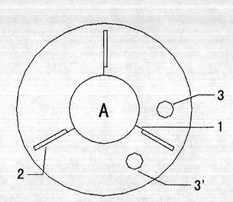
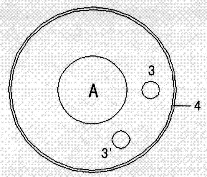
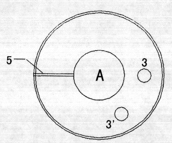
[0015] see figure 1 and figure 2 , the present invention is composed of smooth circular waveguides periodically arranged, each cycle length is composed of loaded circular waveguides and unloaded circular waveguides, and the length of loaded circular waveguides and unloaded circular waveguides can be adjusted according to the required attenuation. A plurality of coupling slots 1 are radiated uniformly along the central hole A on the loaded smooth circular waveguide. The number of coupling slots is not limited, and three are taken as an example in this embodiment. The direction of the coupling slot 1 corresponds to a cuboid attenuation ceramic 2 , and the function of the attenuation ceramic 2 is to absorb the high-frequency field leaked from the coupling slot 1 . There are also two centering holes 3, 3' on the loading circular waveguide, and the two centering holes 3, 3' are symmetrically distributed with the attenuation porcelain 2. The two centering holes present an angle o...


PUM


Abstract

The invention discloses a high-frequency structure for a gyrotron amplifier. A plurality of coupling slots are formed on a loading circular waveguide; a cuboid attenuating porcelain corresponds to each coupling slot direction respectively so as to absorb a high-frequency field leaked by the coupling slots; two centering holes of 60 degrees are formed on the loading circular waveguide and an unloading circular waveguide respectively; and a solder groove is formed on the circumference of the unloading circular waveguide on two sides. The centering method comprises the following steps of: putting a respective centering rod into a central hole and one of the centering holes of the loading circular waveguide; inserting the unloading circular waveguide into the centering rod and pressing; inserting the other loading circular waveguide into the centering rod and pressing along the direction of the centering holes; inserting another unloading circular waveguide along the direction of the centering holes; repeating the operation in turn, and determining the periodicity and the entire length according to the needed attenuation; and pressing the whole circular waveguides and putting the solder into the solder groove for braze welding.

Description

technical field [0001] The invention belongs to the field of microwave technology and can be applied to high-power millimeter-wave devices. Background technique [0002] The cyclotron traveling wave tube amplifier has the characteristics of high power, high gain and broadband in the millimeter wave band, and has broad application prospects and development potential in radar imaging, electronic countermeasures, and anti-stealth target detection. A source of coherent radiation of concern. The high-frequency structure of the cyclotron traveling wave tube is the place where the electron beam interacts with the high-frequency field, and is used to realize the energy transfer from the electron beam to the electromagnetic field. The usual practice is to use a smooth circular waveguide for the interaction structure, and the tube wall is coated with graphite-like absorbing materials to suppress spontaneous oscillations, but it cannot meet the needs of high average power. Contents ...

Claims


Application Information

Patent Timeline
Patent Type & Authority Patents(China)
IPC IPC(8): H01J23/36H01J23/54H01P3/127
Inventor 徐寿喜顾伟刘濮鲲张世昌
Owner INST OF ELECTRONICS CHINESE ACAD OF SCI
Features
  • R&D
  • Intellectual Property
  • Life Sciences
  • Materials
  • Tech Scout
  • Unparalleled Data Quality
  • Higher Quality Content
  • 60% Fewer Hallucinations
Learn More