Radiating device and manufacture method thereof

A technology of heat sink and radiator, applied in elastic/clamping device, cooling/ventilation/heating transformation, circuit arrangement on support structure, etc., can solve the problems of high cost, affect the normal operation of heat sink, etc., and achieve easy installation Effect

Inactive Publication Date: 2010-12-08
FU ZHUN PRECISION IND SHENZHEN +1
View PDF6 Cites 11 Cited by
  • Summary
  • Abstract
  • Description
  • Claims
  • Application Information

AI Technical Summary

Problems solved by technology

The cost of this fixing method is relatively high, and if there is a false welding when assembling the heat pipe, it will directly affect the normal operation of the heat sink

Method used


Image

  • Radiating device and manufacture method thereof
  • Radiating device and manufacture method thereof
  • Radiating device and manufacture method thereof

Examples


Embodiment Construction

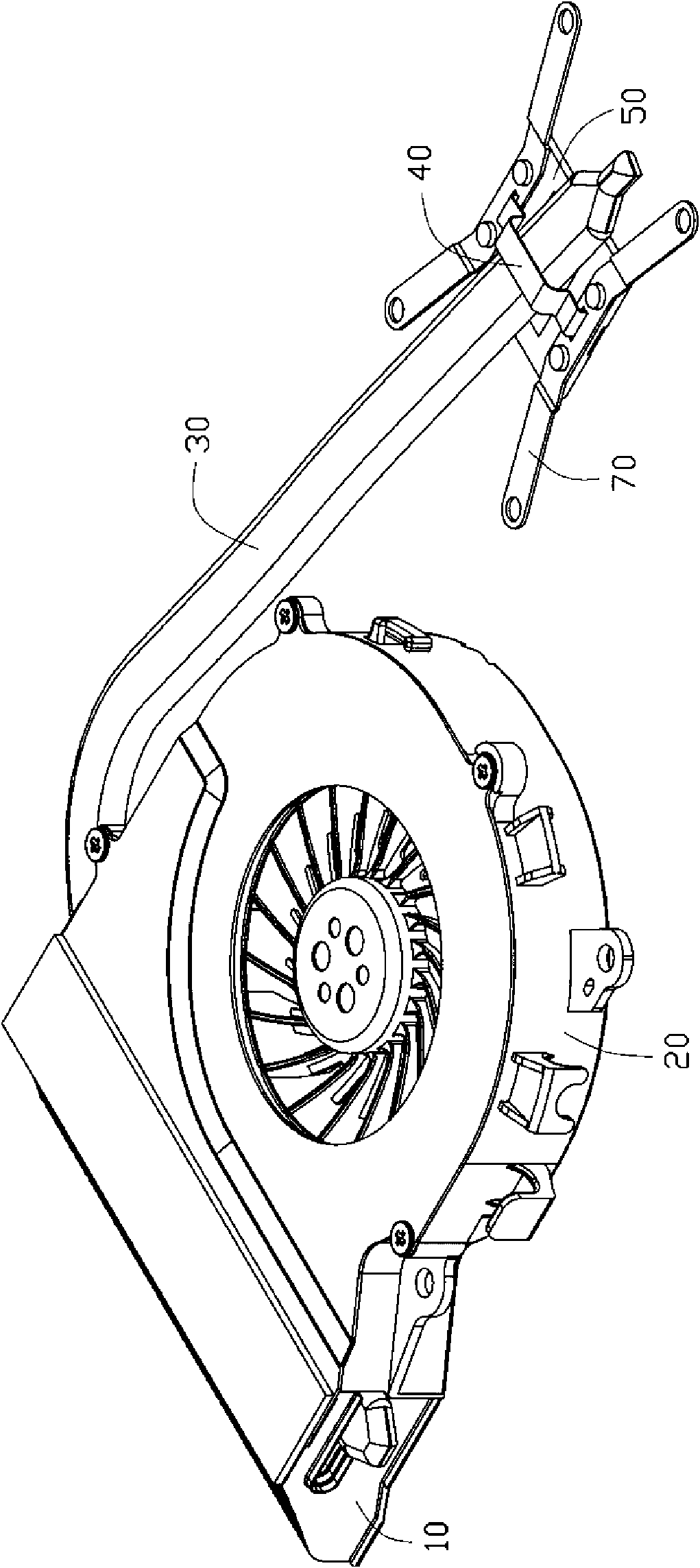
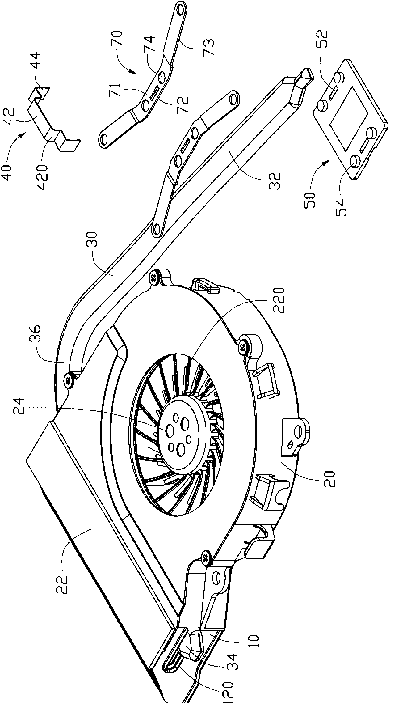
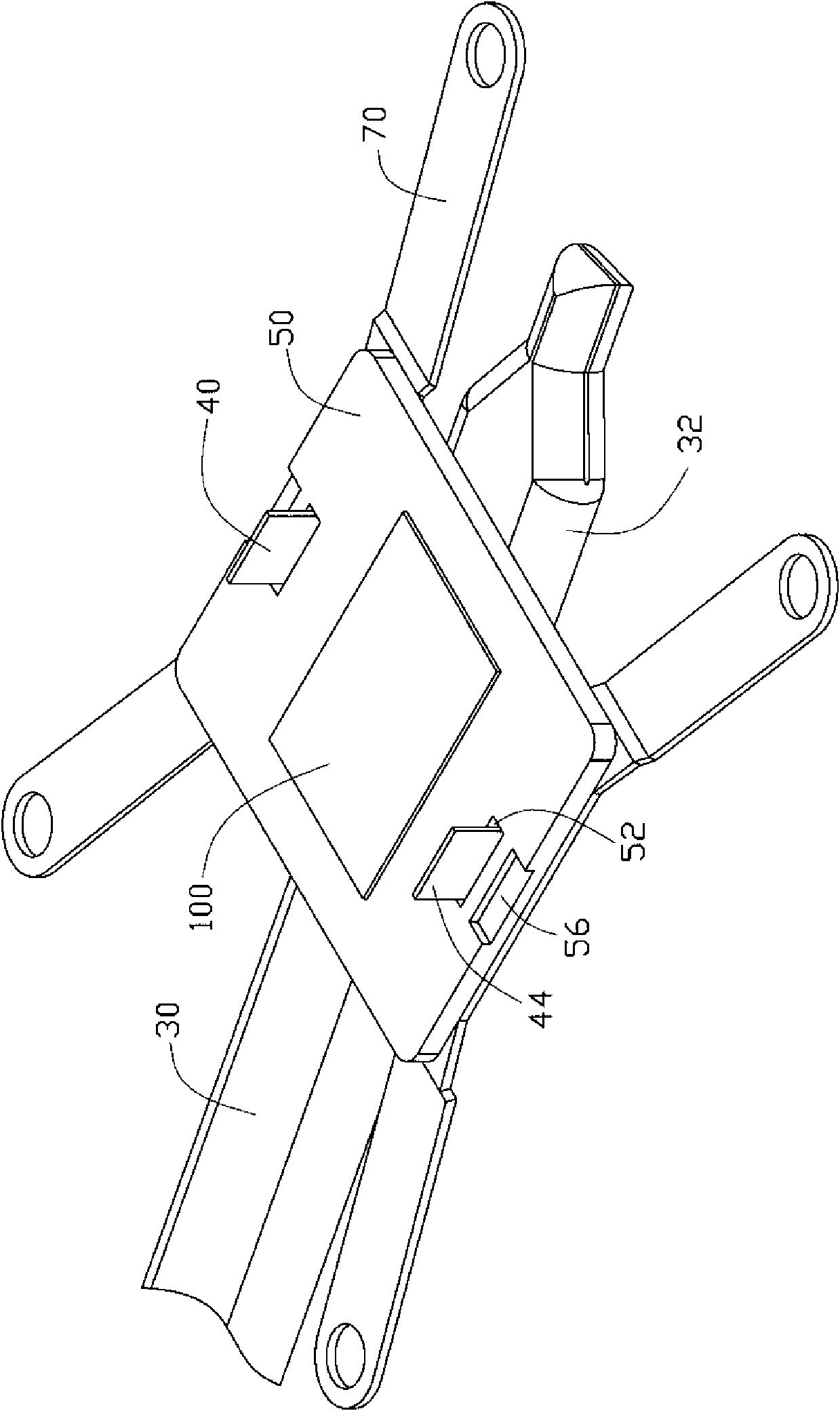
[0016] see Figure 1 to Figure 3 , the heat dissipation device of the present invention is used to dissipate heat from an electronic component 100 mounted on a circuit board (not shown), and it includes a radiator 10, a centrifugal fan 20 positioned at one side of the radiator 10, and the radiator A heat pipe 30 thermally connected to the device 10 , a base plate 50 thermally coupled with the free end of the heat pipe 30 , and a buckle 40 for buckling and fixing the heat pipe 30 on the base plate 50 . The heat dissipation device also includes two elastic pieces 70 placed on the substrate 50 for fixing the substrate 50 to the circuit board.

[0017] The heat sink 10 includes several heat dissipation fins combined with each other. The cooling fins are parallel to each other and arranged vertically. An air flow channel is formed between every two adjacent heat dissipation fins. A gap is formed in the middle of each cooling fin, and these gaps are connected to form a strip-shap...


PUM


Abstract

The invention provides a radiating device, which is used for radiating heat for electric elements arranged on a circuit board. The device comprises a radiator, a substrate for adhering to the electric elements and a heat pipe which is in heat conducting connection with the substrate and the radiator, as well as at least one buckle which comprises a compressing part crossing the heat pipe, wherein two ends of the compressing part form a lock part respectively; two slots passing through the substrate are formed on the substrate corresponding to the lock parts; and the tail ends of the lock parts are bent to be buckled with the substrate after the lock parts pass through the slots, so that the heat pipe is fixed on the substrate. Compared with the prior art, the buckles of the radiating device is compressed on the heat pipe through the compressing part, and the tail ends of the lock parts are bent to be buckled with the substrate to achieve the effect of fixing the heat pipe on the substrate, so the heat pipe and the substrate can be assembled conveniently, are easy for production and are matched firmly. The invention also relates to a method for manufacturing the radiating device.

Description

technical field [0001] The invention relates to a heat dissipation device, in particular to a heat dissipation device for cooling electronic components and a manufacturing method thereof. Background technique [0002] With the rapid development of the electronic information industry, the processing capacity of electronic components such as the central processing unit (CPU) has been continuously improved, resulting in an increase in the heat generated by them. Today, heat dissipation has become an important factor affecting computer performance, and has also become a bottleneck in the practical application of high-speed processors. For ultra-thin models such as notebook computers, heat dissipation is even more important. Under the design of the ultra-thin model, the distance between the heating electronic components such as the central processing unit (CPU) and the upper and lower covers of the casing is very close. In order to efficiently remove the heat generated by the el...

Claims


Application Information

Patent Timeline
Patent Type & Authority Applications(China)
IPC IPC(8): H05K7/20H05K7/12H01L23/34H01L23/40
CPCH01L23/467H01L23/4093H01L23/427H01L2023/4087H01L2023/4056H01L2924/0002Y10T29/4935H01L2924/00
Inventor 杨红成聂伟成孔程
Owner FU ZHUN PRECISION IND SHENZHEN
Why Eureka
Try Eureka