Dehumidifying device

A technology of air volume and refrigerant, applied in the direction of heating method, lighting and heating equipment, application, etc., can solve the problems such as the limitation of the improvement of dehumidification capacity and the reduction of dehumidification capacity.

Active Publication Date: 2010-12-08
PANASONIC CORP
View PDF1 Cites 20 Cited by
  • Summary
  • Abstract
  • Description
  • Claims
  • Application Information

AI Technical Summary

Problems solved by technology

However, since the absolute amount of moisture contained in the air is very small, it is impossible to make the supplied air into a state that is prone to condensation (increase the moisture content and increase the relative humidity), and there is a limit to the improvement of the dehumidification capacity.
[0005] In addition, when the room temperature is low as in winter, since frost adheres to the heat absorber (covered state), it must be operated while defrosting, and the dehumidification capacity is significantly reduced.

Method used


Image

  • Dehumidifying device
  • Dehumidifying device
  • Dehumidifying device

Examples


no. 1 approach

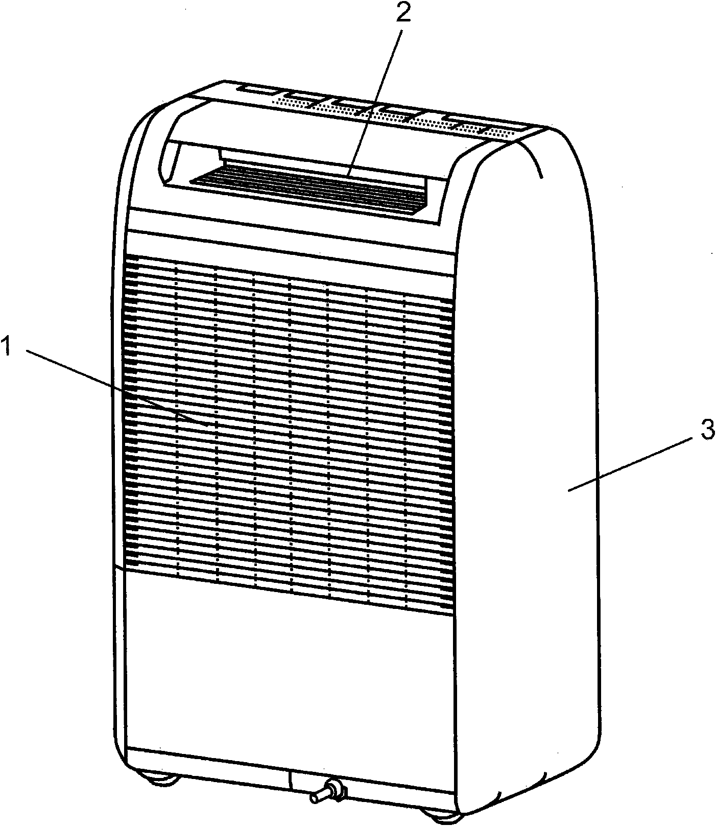
[0028] Next, a first embodiment of the present invention will be described with reference to the drawings. figure 1 It is an external perspective view of the dehumidifier in Embodiment 1 of this invention. Such as figure 1 As shown, the dehumidifier of this embodiment includes: a main body casing 3 having an air inlet 1 and an exhaust port 2; figure 2 Shown, constitutes the refrigeration cycle mechanism 4 of the heat pump. In addition, a blower 9 including a motor, an impeller, and the like is provided inside the main body casing 3 , and the blower 9 sucks in air from the air inlet 1 and blows the air into the main body casing 3 . Moreover, the dehumidification rotor 10 which has the moisture release part 11 and the moisture absorption part 12 is provided in the main body case 3. As shown in FIG. The dehumidification rotor 10 is driven to rotate by a drive unit 15 including a motor, gears, and the like.

[0029] The refrigeration cycle mechanism 4 is composed of a compres...

no. 2 approach

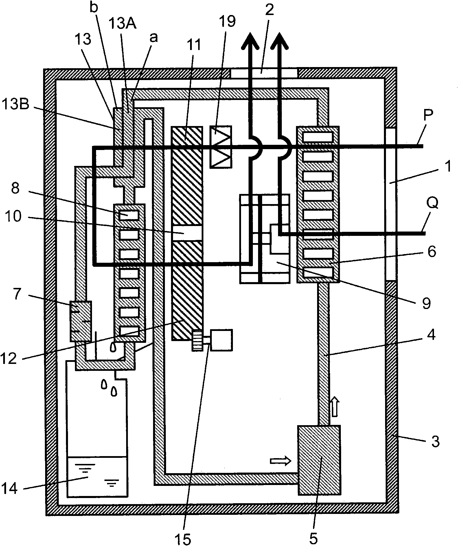
[0043] Figure 10 It is a schematic cross-sectional structural view of the dehumidifier in the second embodiment of the present invention. exist Figure 10 In the dehumidifier of this embodiment, the main body casing 3 is formed with the first air inlet 1A, the second air inlet 1B, and the air outlet 2 . The first air inlet 1A and the second air inlet 1B are formed on the side surface which is the outer peripheral surface of the main body case 3 , and the exhaust port 2 is formed on the upper surface of the main body case 3 . The second air inlet 1B is formed at a position lower than the first air inlet 1A on the outer periphery of the main body case 3 .

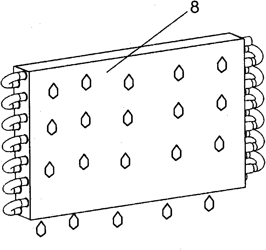
[0044] Inside the main body casing 3 is provided a refrigeration cycle mechanism 4 constituting a heat pump. The refrigeration cycle mechanism 4 is composed of a compressor 5 , and a radiator 6 , an expander 7 , and a heat absorber 8 sequentially provided downstream of the compressor 5 . Moreover, the desiccant rotor 10 ...


PUM


Abstract

A dehumidifying device achieves improved dehumidifying ability by having a body case (3) provided with a suction opening (1) and a discharge opening (2), a refrigeration cycle mechanism (4) provided in the body case (3), a fan (9) for sucking air into the body case (3) from the suction opening (1) and forming an air flow path in which the sucked air is sent to the discharge opening (2) after being passed through a heat dissipater (6) and a heat absorber (8) in that order, a moisture releasing section (11) of a dehumidifying rotor (10) located in the air flow path and provided between the heatdissipater (6) and the heat absorber (8), a moisture absorbing section (12) of the dehumidifying rotor (10) located in the air flow path and provided between the heat absorber (8) and the discharge opening (2), and a refrigerant heat exchanger (13) located in the air flow path and provided between the humidity discharging section (11) and the heat absorber (8).

Description

technical field [0001] The present invention relates to a dehumidifier equipped with a refrigeration cycle mechanism. Background technique [0002] A conventional dehumidifier of this type described in, for example, Patent Document 1 has the following configuration. That is, it includes: a main body case having an intake port and an exhaust port; and a refrigeration cycle mechanism provided in the main body case. The refrigeration cycle mechanism is composed of a compressor, and a radiator, an expander, and a heat absorber arranged downstream of the compressor in this order. Moreover, a blower is provided, and the blower blows the air sucked into the main body casing from the air inlet to the air outlet through the radiator and the heat absorber in sequence. [0003] Such a conventional dehumidifier is a device that dehumidifies indoor air by dehumidifying it by dew condensation in a heat absorber. In the refrigeration cycle mechanism, since refrigerant supplied to the co...

Claims


Application Information

Patent Timeline
IPC IPC(8): B01D53/26F24F1/02
CPCB01D53/0438F24F1/025F24F2203/1016F24F3/1423F24F2203/1084B01D2259/40088F24F2203/1068B01D2259/4508B01D53/261F24F1/022F24F1/04
Inventor 藤井泰树胜见佳正堀达也
Owner PANASONIC CORP
Why Eureka
Try Eureka