Sprayed paint drying device

A technology of drying device and drying chamber, which is applied in cleaning device, device for coating liquid on the surface, transportation and packaging, etc. It can solve the problems that the wind cannot control the temperature and the drying effect is poor, so as to reduce the wind speed, Improve residence time and facilitate cleaning effect

Inactive Publication Date: 2018-11-02
JIANGSU ZIQIANG COATING MACHINERY
View PDF0 Cites 1 Cited by
  • Summary
  • Abstract
  • Description
  • Claims
  • Application Information

AI Technical Summary

Problems solved by technology

[0002] As we all know, the paint spray drying device is an auxiliary device used to dry the painted workpiece so as to better attach the sprayed paint to the workpiece. It has been widely used in the drying field. The use of; the existing paint drying device includes an oven, a base plate, two groups of left legs, two groups of right legs and a transmission device, the bottom of the oven is connected to the top of the base plate, and the inside of the oven is provided with a drying chamber, The left end and the right end of the oven are respectively provided with an inlet and an outlet. The right end of the conveying device extends from the left end of the oven through the inlet to the inside of the drying chamber and extends from the left end of the outlet to the outside of the right end of the oven. The top of the oven is provided with a blower. And the output end of the blower communicates with the inside of the top of the oven through the air supply pipe, the bottom of the oven is provided with an exhaust fan, and the input end of the exhaust fan communicates with the inside of the bottom of the oven through the exhaust pipe, and the tops of the two sets of left legs They are respectively connected to the left front side and the left rear side of the bottom end of the base plate, and the tops of the two groups of right outriggers are respectively connected to the right front side and the right rear side of the bottom end of the base plate; The power supply is electrically connected, and then the conveying device is turned on, and the workpiece to be dried is placed on the conveying device, and driven by the conveying device, it enters the drying chamber from the inlet of the oven for drying, and is sent out from the outlet after drying, and then manually Just remove the dried workpiece and carry out the next step of process treatment; it is found in the use of the existing paint drying device that the temperature of the air generated by the blower cannot be controlled, resulting in poor drying effect; at the same time, the exhaust gas discharged by the exhaust fan It is directly discharged to the outside and pollutes the environment, resulting in low reliability in use; and the surface of the conveying device is often dirty after use. Since most of the conveying device is located in the drying chamber, it is inconvenient to clean, and long-term dirt will affect the spraying. Contamination of the final workpiece, resulting in poor practicability

Method used


Image

  • Sprayed paint drying device
  • Sprayed paint drying device
  • Sprayed paint drying device

Examples


Embodiment Construction

[0021] The specific implementation manners of the present invention will be further described in detail below in conjunction with the accompanying drawings and embodiments. The following examples are used to illustrate the present invention, but are not intended to limit the scope of the present invention.

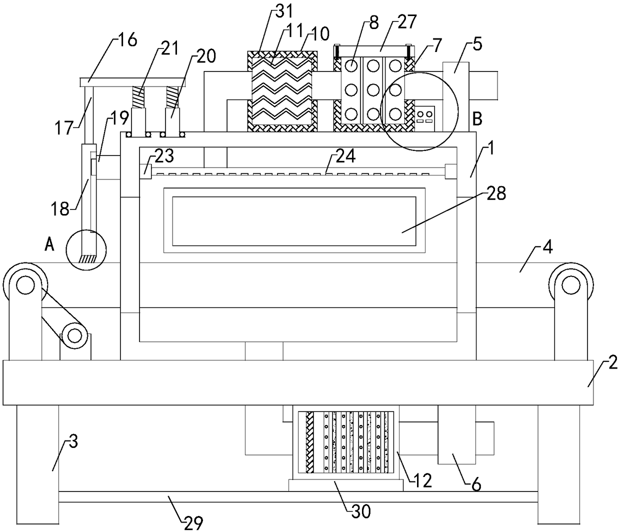
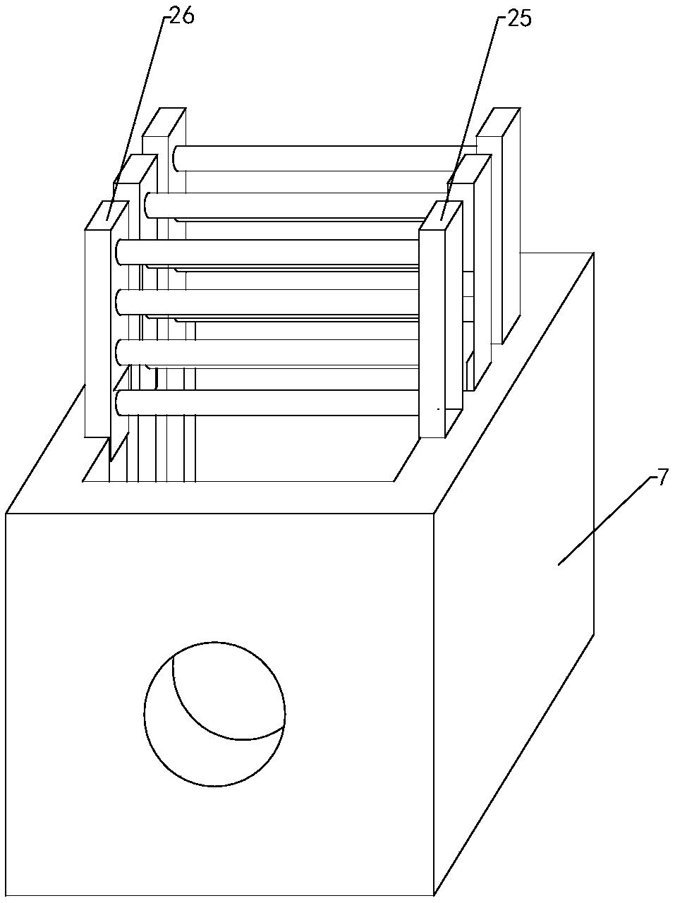
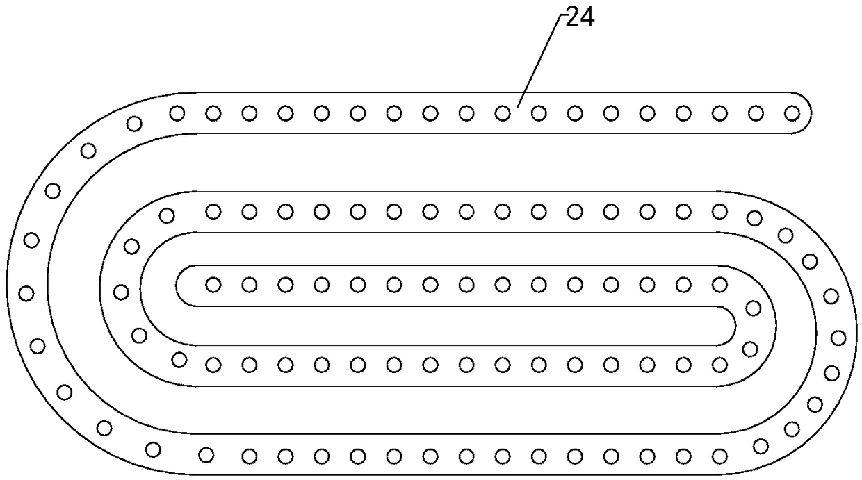
[0022] like Figure 1 to Figure 8Shown, a kind of spray paint drying device of the present invention comprises oven 1, base plate 2, two groups of left legs 3, two groups of right legs and conveying device 4, the bottom of oven is connected with the top of base plate, and the top of oven There is a drying chamber inside, and the left and right ends of the oven are respectively provided with an inlet and an outlet. The right end of the transmission device extends from the left end of the oven through the inlet to the inside of the drying chamber and extends from the left end of the outlet to the outside of the right end of the oven. The top of the oven is provided with a b...


PUM


Abstract

The invention relates to the technical field of drying accessory devices, in particular to a sprayed paint drying device. The temperature of air generated by a supply fan of the drying device can be controlled, drying effects are improved, exhaust gas discharged by an exhaust fan can be treated, environmental pollution is prevented, use reliability of the device is improved, dirt substances on thesurface of a conveying device can be conveniently cleaned, pollution of a sprayed workpiece is prevented, and practicability is improved. The drying device comprises a drying box, a bottom plate, twogroups of left supporting legs, two groups of right supporting legs, a conveying device, a heating box, three groups of first heating bars, three groups of second heating bars, three groups of thirdheating bars, a controller, a buffering box, a treatment box, a filtering screen, multi-group photocatalyst carriers, multi-group ultraviolet lamp pipes, an adjusting plate, two groups of lifting rods, a brush plate, a supporting block, two groups of threaded pipes and two groups of threaded rods, a sliding block is arranged at the left end of the supporting block, a sliding groove is longitudinally formed into the right end of the brush plate, a slider is slidably matched with the inside of the sliding groove, and bristles are arranged at the bottom end of the brush plate.

Description

technical field [0001] The invention relates to the technical field of drying accessory devices, in particular to a paint spraying drying device. Background technique [0002] As we all know, the paint spray drying device is an auxiliary device used to dry the painted workpiece so as to better attach the sprayed paint to the workpiece. It has been widely used in the drying field. The use of; the existing paint drying device includes an oven, a base plate, two groups of left legs, two groups of right legs and a transmission device, the bottom of the oven is connected to the top of the base plate, and the inside of the oven is provided with a drying chamber, The left end and the right end of the oven are respectively provided with an inlet and an outlet. The right end of the conveying device extends from the left end of the oven through the inlet to the inside of the drying chamber and extends from the left end of the outlet to the outside of the right end of the oven. The top...

Claims


Application Information

Patent Timeline
Patent Type & Authority Applications(China)
IPC IPC(8): B05D3/04B01D46/10B01D53/00B65G45/18
CPCB05D3/0413B01D46/10B01D53/007B01D2257/70B01D2259/804B65G45/18
Inventor 吕海波宋友高
Owner JIANGSU ZIQIANG COATING MACHINERY
Why Eureka
Try Eureka