Tea maker
A tea machine and tea basket technology, which is applied to beverage preparation devices, household appliances, applications, etc., can solve the problems of unevenness of tea water, cannot realize automatic separation of tea leaves and water, etc., and achieves low cost and accurate automatic control of tea brewing time. , the effect of convenient placement
- Summary
- Abstract
- Description
- Claims
- Application Information
AI Technical Summary
Problems solved by technology
Method used
Image

Examples
specific Embodiment 1
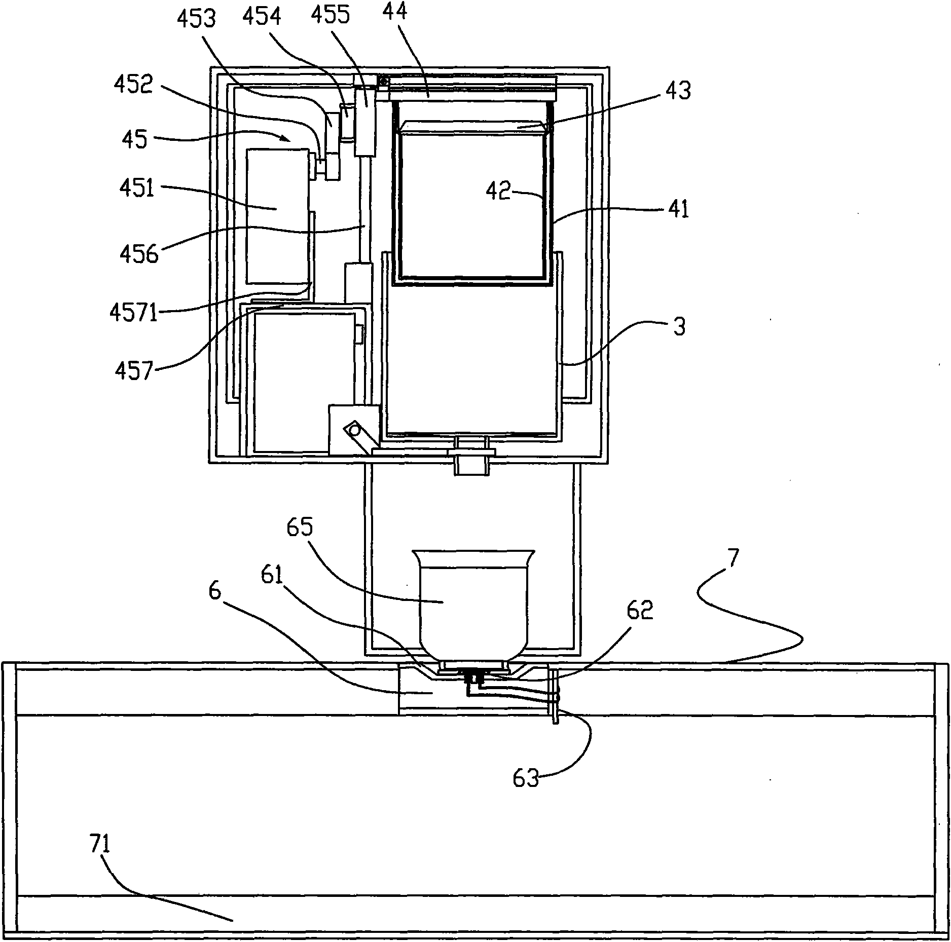
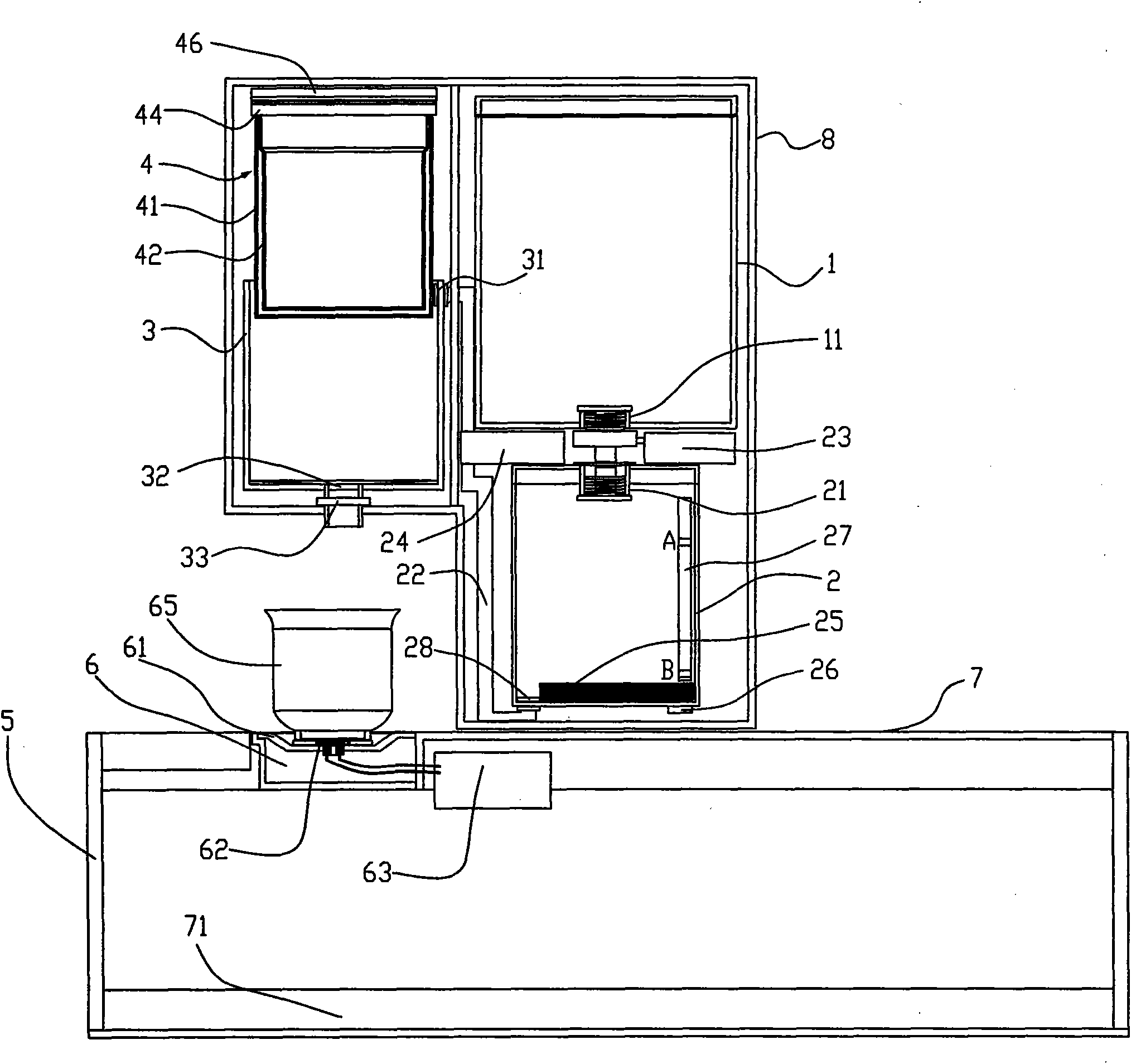
[0053] Such as figure 1 , figure 2 As shown, this embodiment includes a water tank 1, a boiling water cup 2, a tea cup 3, a tea basket assembly 4, a bracket 457 close to the tea cup 3, a control circuit, and a drive for driving the tea basket 41 arranged in the body 8. The lifting mechanism 45 of lifting. The water tank 1 is connected above the kettle 2 , and a solenoid valve I23 is connected between the water outlet I11 of the water tank 1 and the water inlet I21 of the kettle 2 . The water outlet II 28 of the boiling water cup 2 is connected with the water inlet II31 of the tea making cup 3 through the pipeline 22, and the water pump 24 is also connected in the pipeline 22, and the water outlet III32 of the tea making cup 3 A solenoid valve II33 is connected. The bottom of the kettle 2 is provided with a heating element 25 , a temperature sensor 26 and a water level detection device 27 . The tea basket assembly 4 includes a tea basket 41, a tea basket cover 46, a frame ...
specific Embodiment 2
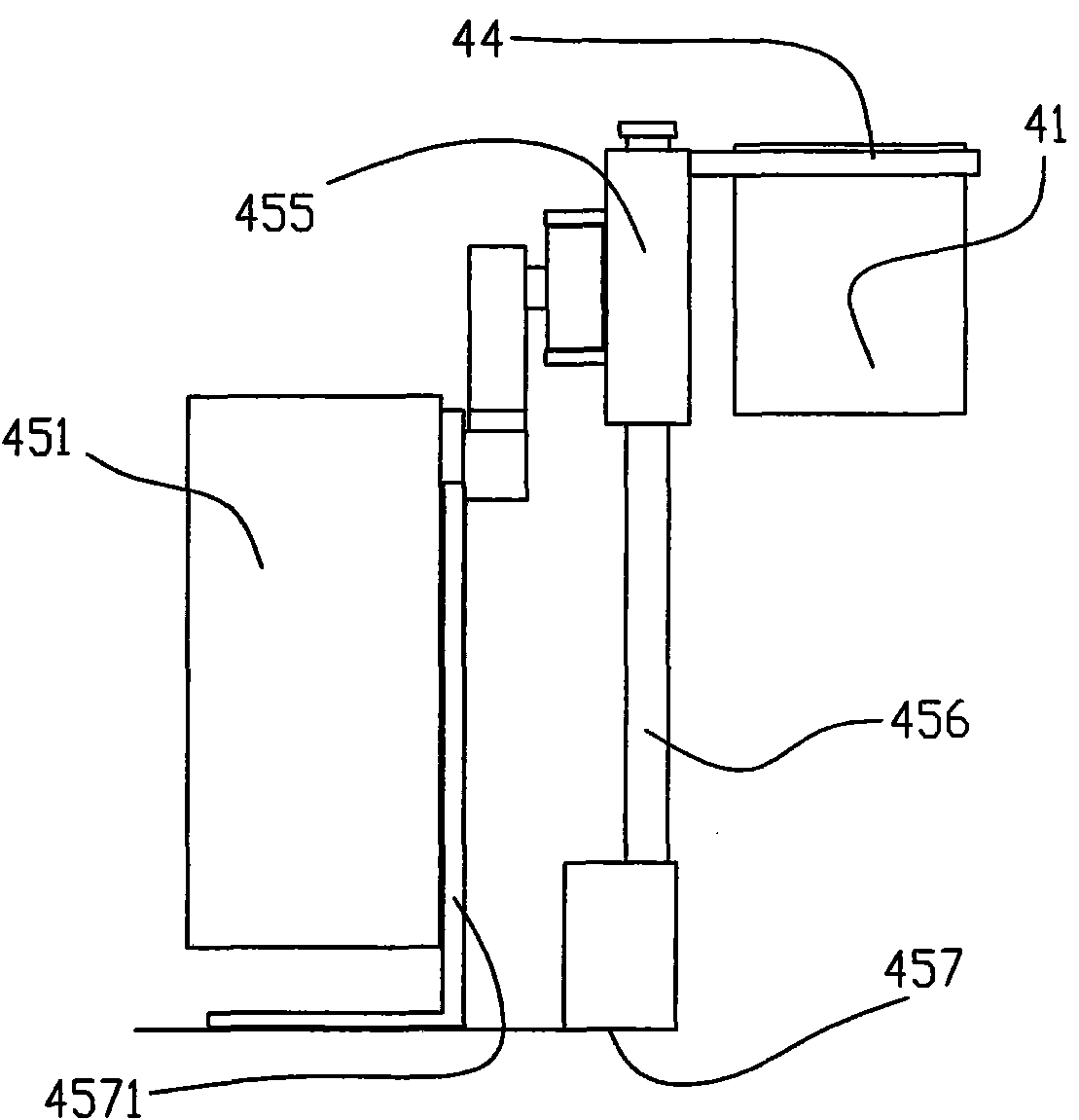
[0077] Compared with the solution in the first embodiment, the main difference of this embodiment is that a lifting mechanism 45 with a different working mode is provided. Such as Figure 5 , Figure 6 As shown, in this embodiment, the guide rail is a horizontal flange I4552, the driving rod 453 is a crank structure, and a slider is hinged on the joint between the driving rod 453 and the guide rail, and the slider presses On the upper end surface of the horizontal flange I4552, between the lower end surface of the sliding frame 455 and the bracket 457, a return spring I4555 is provided. In this embodiment, the slider is a structure of a pulley 454 , and the pulley 454 is hingedly connected with the driving rod 453 .
[0078] The operating principle of the lifting mechanism 45 described in this embodiment is as follows:
[0079] Such as Figure 5 , Figure 6 As shown, the power supply of the motor 451 is turned on (assuming that the carriage 455 is at the upper limit posit...
specific Embodiment 3
[0081] Compared with the solution in the first embodiment, the main difference of this embodiment is that another working mode of the lifting mechanism 45 is provided. Such as Figure 7 , Figure 8 As shown, in this embodiment, the guide rail is a horizontal flange II 4553, the driving rod 453 is a crank structure, and a sliding block is hinged on the joint between the driving rod 453 and the horizontal flange II 4553, The lower end surface of the horizontal flange II 4553 presses on the slider, and a return spring II 4556 is provided between the upper end surface of the sliding frame 455 and the bracket 457 . In this embodiment, the slider is a structure of a pulley 454 , and the pulley 454 is hingedly connected with the driving rod 453 .
[0082] The operating principle of the lifting mechanism 45 described in this embodiment is as follows:
[0083] Such as Figure 7 , Figure 8 As shown, the power supply of the motor 451 is turned on (assuming that the carriage 455 is ...
PUM
 Abstract
Description
Claims
Application Information
 - Generate Ideas
- Intellectual Property
- Life Sciences
- Materials
- Tech Scout
- Unparalleled Data Quality
- Higher Quality Content
- 60% Fewer Hallucinations
Browse by: Latest US Patents, China's latest patents, Technical Efficacy Thesaurus, Application Domain, Technology Topic, Popular Technical Reports.
© 2025 PatSnap. All rights reserved.Legal|Privacy policy|Modern Slavery Act Transparency Statement|Sitemap|About US| Contact US: help@patsnap.com