
Dynamic below-knee artificial limb containing flexible dynamic ankle joints and toe joints

An ankle joint with flexible technology, applied in the direction of artificial legs, etc., can solve the problems of high noise, unsatisfactory, low control precision, etc., and achieve the effects of good flexible dynamic characteristics, good impact resistance, and improved energy efficiency

Active Publication Date: 2010-12-15
PEKING UNIV
View PDF4 Cites 44 Cited by
  • Summary
  • Abstract
  • Description
  • Claims
  • Application Information

AI Technical Summary

Problems solved by technology

Although these three drivers have their own advantages, none of them can meet the requirements of below-knee powered prostheses, which have high requirements for power, flexibility and precision.
Although the motor has high control precision, it cannot provide huge torque instantly, and the flexibility and shock resistance of the motor are poor
Although hydraulic and pneumatic drives have certain flexibility and can provide huge torque instantaneously, they have low control accuracy, high noise and large volume.

Method used


Image

  • Dynamic below-knee artificial limb containing flexible dynamic ankle joints and toe joints
  • Dynamic below-knee artificial limb containing flexible dynamic ankle joints and toe joints
  • Dynamic below-knee artificial limb containing flexible dynamic ankle joints and toe joints

Examples


Embodiment Construction

[0015] The present invention will be described in detail below in conjunction with the accompanying drawings and embodiments.

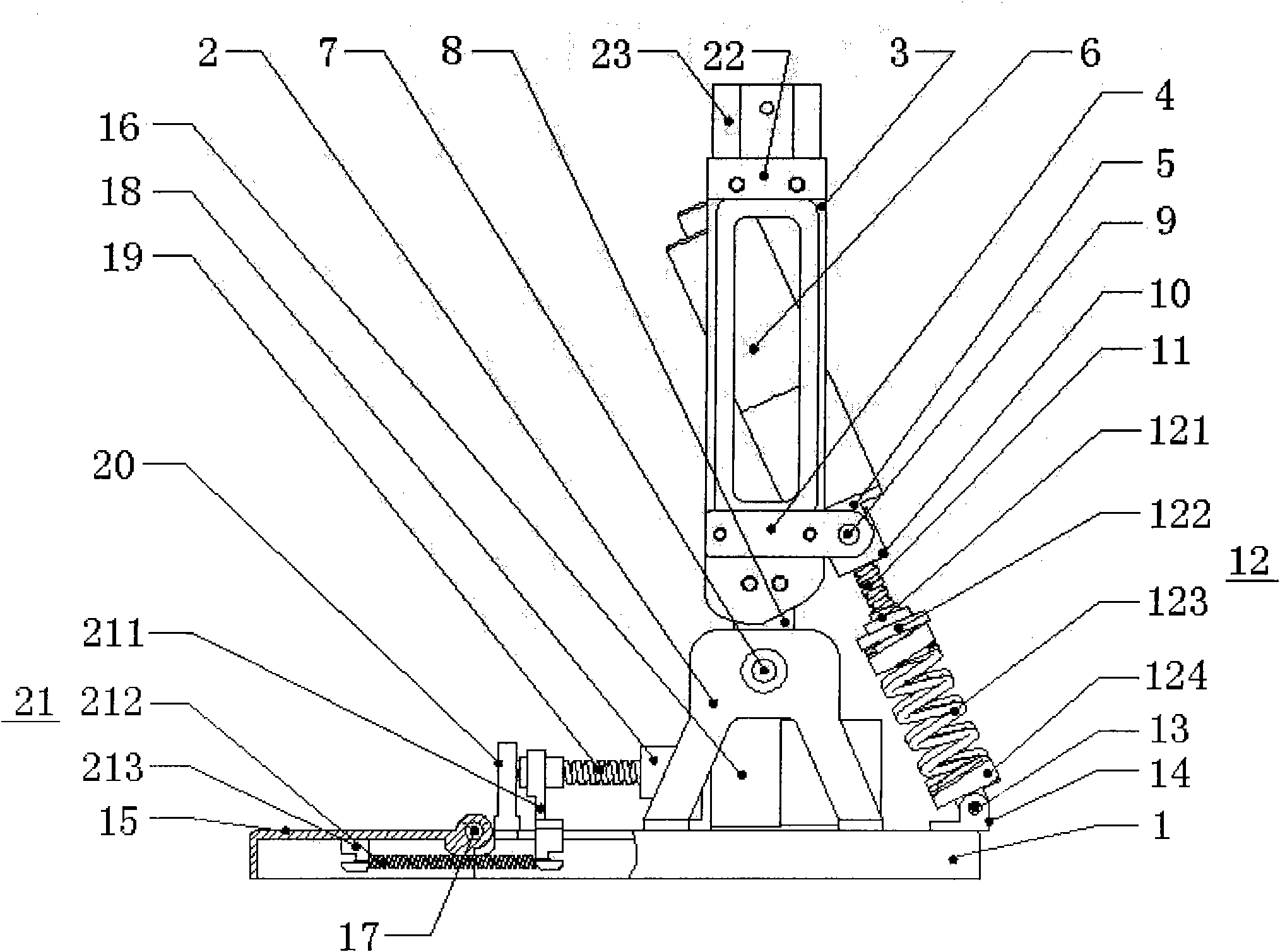
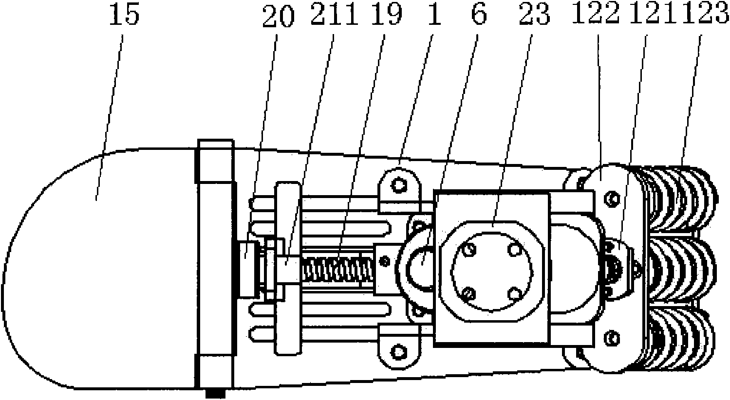
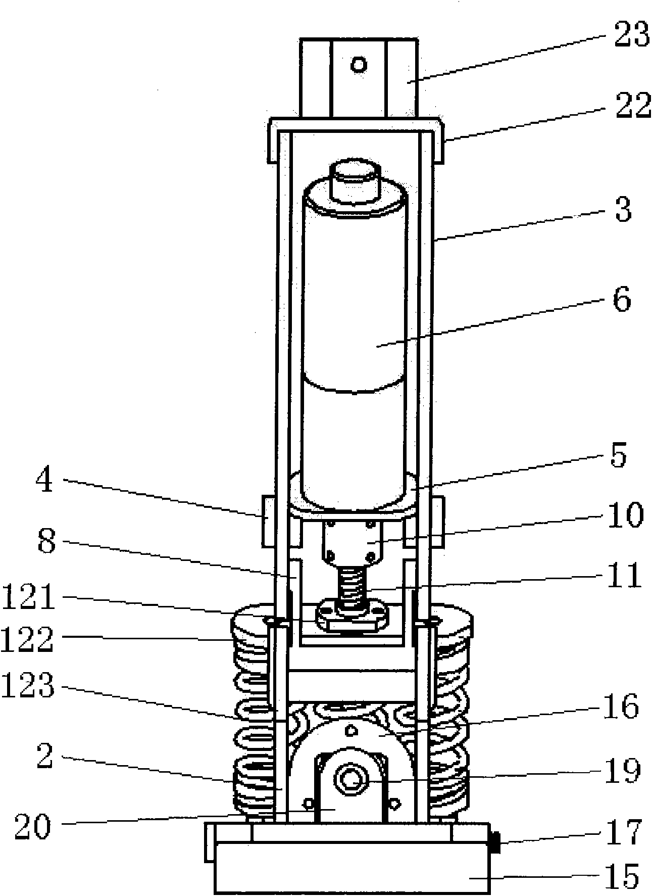
[0016] Such as Figure 1 ~ Figure 3 Shown, the present invention comprises two parts of ankle joint kinematic mechanism and toe joint kinematic mechanism, and wherein ankle joint kinematic mechanism comprises a rear sole 1, an ankle joint support frame 2, two calf baffles 3, two ankle joint motor connecting frames 4 , an ankle joint motor fixing frame 5 and an ankle joint motor 6 . The ankle support frame 2 is fixedly connected to the rear sole 1 top, the upper end of the ankle joint support frame 2 is hinged with the lower end of an ankle joint shaft connection frame 8 through an ankle joint shaft 7, and the upper end of the ankle joint shaft connection frame 8 is fixedly connected to the two sides. Between calf baffles 3. Two ankle joint motor connection frames 4 are respectively fixedly connected to the outsides of the two shank baffle plates 3, ...


PUM


Abstract

The invention relates to a dynamic below-knee artificial limb containing flexible dynamic ankle joints and toe joints, which is characterized by comprising an ankle joint moving mechanism and a toe joint moving mechanism, wherein the ankle joint moving mechanism comprises a back sole, an ankle joint supporting frame, shank baffle plates and an ankle joint motor; the ankle joint supporting frame is fixed at the upper part of the back sole, and the upper end of the ankle joint supporting frame is articulated with an ankle joint shaft connecting frame connected between two shank baffle plates; the ankle joint motor is fixedly connected between the two shank baffle plates, the output end of the ankle joint motor is fixedly connected with one end of an ankle joint screw through a shaft coupling, and the other end of the screw is connected with the back sole through an ankle joint spring mechanism; the toe joint moving mechanism comprises a front sole and a toe joint motor, wherein the front sole is articulated with the back sole, and the toe joint motor is fixedly connected with the back sole; an output shaft of the toe joint motor is fixedly connected with one end of a toe joint screw through a shaft coupling, and the other end of the screw is articulated with a toe joint screw fixing frame; and the toe joint screw is connected with the front sole through a toe joint spring mechanism. The dynamic below-knee artificial limb can be widely applied to the researches on the flexible dynamic joints of artificial limbs and serves the handicapped.

Description

technical field [0001] The invention relates to the technical field of intelligent bionic machinery, in particular to a dynamic under-knee prosthesis containing flexible dynamic ankle joints and toe joints based on the combination of active and passive movement modes. Background technique [0002] Every year, tens of thousands of disabled people suffer lower limb amputation due to various natural disasters, diseases and traffic accidents. These disabled people have lost their ability to work due to lower limb amputation, and even cannot take care of themselves. In order to restore their ability to work and improve their quality of life, they are in urgent need of artificial limbs. [0003] However, the current level of below-the-knee prosthetics is still very backward. Traditional below-the-knee prostheses simply imitate human lower limbs in shape, and their ankle joints are fixed or can only be passively bent and rotated within a small range of angles. Although such pros...

Claims


Application Information

Patent Timeline
Patent Type & Authority Applications(China)
IPC IPC(8): A61F2/60
Inventor 朱金营王启宁袁克彬王龙
Owner PEKING UNIV
Learn More