Crystal block slicing method

A technology for slicing and ingots, which is applied to fine working devices, stone processing equipment, manufacturing tools, etc., can solve problems such as steel wire slippage, high ratio, and reduced slicing yield, and achieve the quality of silicon wafers Effects of improvement, line mark reduction, and yield assurance

Inactive Publication Date: 2010-12-15
TRINA SOLAR CO LTD
View PDF2 Cites 11 Cited by
  • Summary
  • Abstract
  • Description
  • Claims
  • Application Information

AI Technical Summary

Problems solved by technology

[0002] At present, when slicing single crystal and polycrystalline ingots, usually before the ingot enters the slicing machine for slicing, the ingot is first glued to the surface of the crystal support in parallel, and at the same time, two or two More than one guide bar, the guide bar guides and fixes the steel wire as much as possible to reduce the steel wire when slicing. When the steel wire just touches the surface of the crystal block, since any single steel wire is parallel to the surface of the crystal block, they are all in line contact, and the contact

Method used


Image

  • Crystal block slicing method
  • Crystal block slicing method

Examples


Embodiment Construction

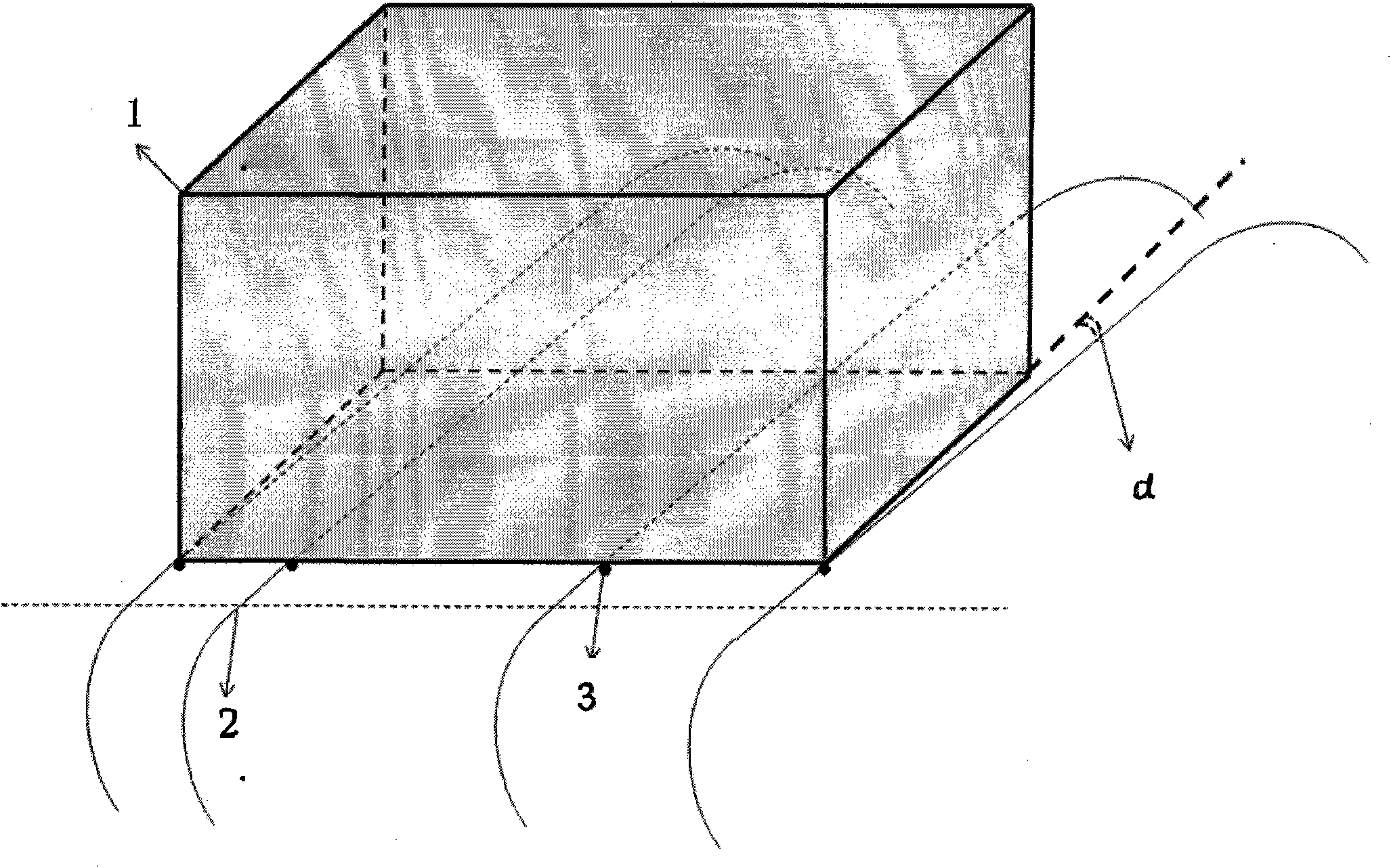
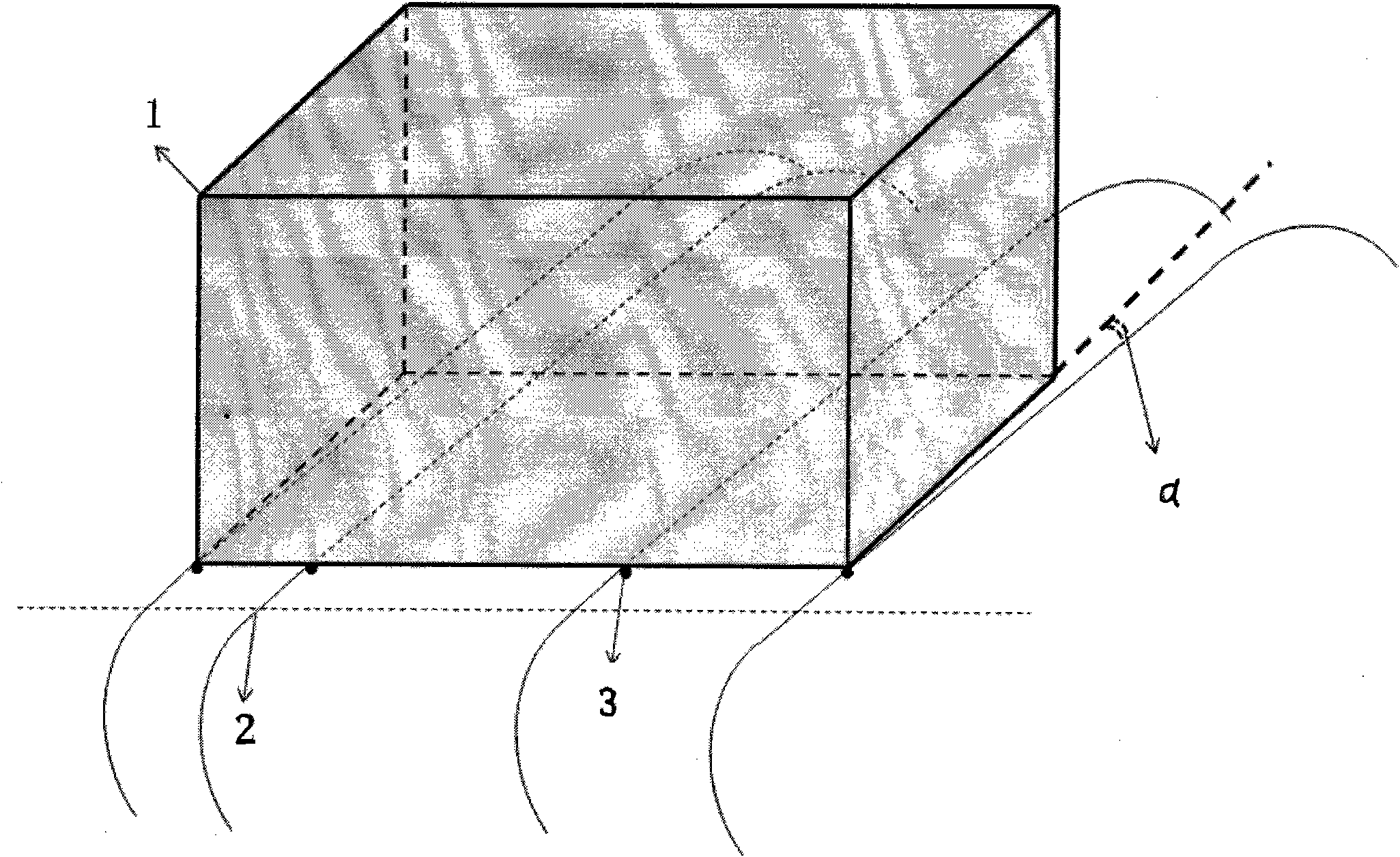
[0013] Such as figure 1 As shown, a crystal block slicing method, the silicon block 1 to be sliced ​​is placed in a slicer, the cutting surface of the silicon block 1 to be sliced ​​and the slicing wire mesh form a certain angle α, when the slicing wire mesh is cut , the steel wire 2 in the slicing wire network is in point contact with the side edge of the cut surface of the silicon block 1, and the black dot in the figure shows the contact point 3.

[0014] The production method is as follows:

[0015] (1) Carry out prescribing, testing, truncation, chamfering, grinding and other processes on polycrystalline ingots to make finished polycrystalline ingots; for single crystal ingots, truncation, testing, edge cutting, truncation, chamfering, Grinding and other processes to make finished single crystal ingots;

[0016] (2) Clean the finished crystal blocks and auxiliary materials such as glass plates in an ultrasonic tank covered with a soft rubber pad and filled with an appro...


PUM

PropertyMeasurementUnit
Angleaaaaaaaaaa

Abstract

The invention relates to the technical fields of crystal block slicing and silicon slice preparation, in particular to a crystal block slicing method. The method comprises the following steps of: putting a silicon block to be sliced into a slicer, forming a certain included angle between the sliced surface of the silicon block to be sliced with a slicing wire mesh, and when the slicing wire mesh slices, forming point contact of steel wires in the slicing wire mesh with the side edge of the sliced surface of the silicon block. The method avoids the line contact of a single steel wire with the surface of the crystal block when the steel wires just contact the surface of the crystal block during slicing, the single steel wire forms the point contact with the surface of the crystal block, the contact area is small, the steel wires are easy to slice into the crystal block, and the slipping phenomenon when the line-contact steel wires slice the surface of the crystal block is completely avoided.

Description

technical field [0001] The invention relates to the technical field of crystal block slicing and silicon wafer preparation, in particular to a crystal block slicing method. Background technique [0002] At present, when slicing single crystal and polycrystalline ingots, usually before the ingot enters the slicing machine for slicing, the ingot is first glued to the surface of the crystal support in parallel, and at the same time, two or two More than one guide bar, through the guiding and fixing effect of the guide bar on the steel wire, minimize the steel wire when slicing. When the steel wire just touches the surface of the crystal block, since any single steel wire is parallel to the surface of the crystal block, they are all in line contact, and the contact area is large. As a result, the steel wire slips on the entry-cut surface. However, this cutting process cannot completely solve the phenomenon that the steel wire slips on the entry-cut surface. During the slicing pr...

Claims


Application Information

Patent Timeline
IPC IPC(8): B28D5/04
Inventor 贺洁徐云波
Owner TRINA SOLAR CO LTD
Why Eureka
Try Eureka