Method for removing blockage of oil-water well through magnetic positioning pulse acidification

A magnetic positioning, oil-water well technology, applied in the direction of earthwork drilling, wellbore/well components, production fluids, etc., can solve the problems of difficult acid liquid, large impact on reservoirs, water channeling, etc., to improve processing efficiency, Improvement of the profile and the effect of increasing the processing radius

Inactive Publication Date: 2010-12-15
PETROCHINA CO LTD
View PDF3 Cites 15 Cited by
  • Summary
  • Abstract
  • Description
  • Claims
  • Application Information

AI Technical Summary

Problems solved by technology

Conventional plugging removal methods include acidification, deflagration fracturing, fracturing, etc., but deflagration fracturing and fracturing have a relatively large impact on the reservoir. First, it is easy to cause artificial fractures to communicate with natural fractures and cause water channeling. Rapid water breakthrough in oil production wells; second, the stimulation action point cannot be accurately controlled, and it is difficult to achieve selective or uniform plugging removal, which is difficult for profile stimulation
The treatment radius of the acidizing operation is limited, and it is difficult for the acid liquid to go deep into the formation to remove the deep clogging of the reservoir

Method used


Image

  • Method for removing blockage of oil-water well through magnetic positioning pulse acidification
  • Method for removing blockage of oil-water well through magnetic positioning pulse acidification
  • Method for removing blockage of oil-water well through magnetic positioning pulse acidification

Examples


Embodiment 1

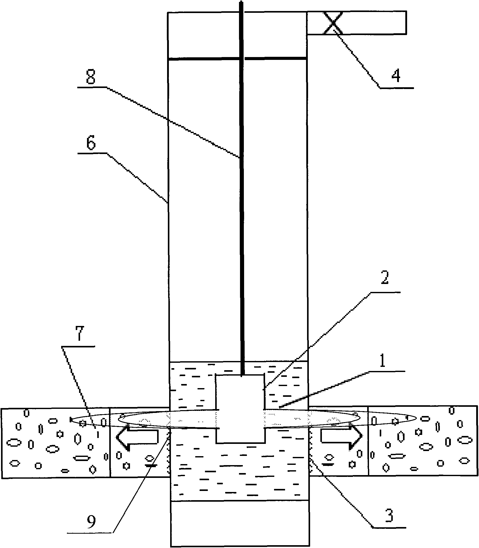
[0026] Example 1: An oil well with an inner diameter of casing 6 of 120 mm, a well depth of 2400 meters, a thickness of reservoir 7 of 5 meters, and a position of reservoir 7 of 2000-2005 meters, using the magnetic positioning pulse acidizing method for oil-water wells As an example, the present invention will be further described in detail.

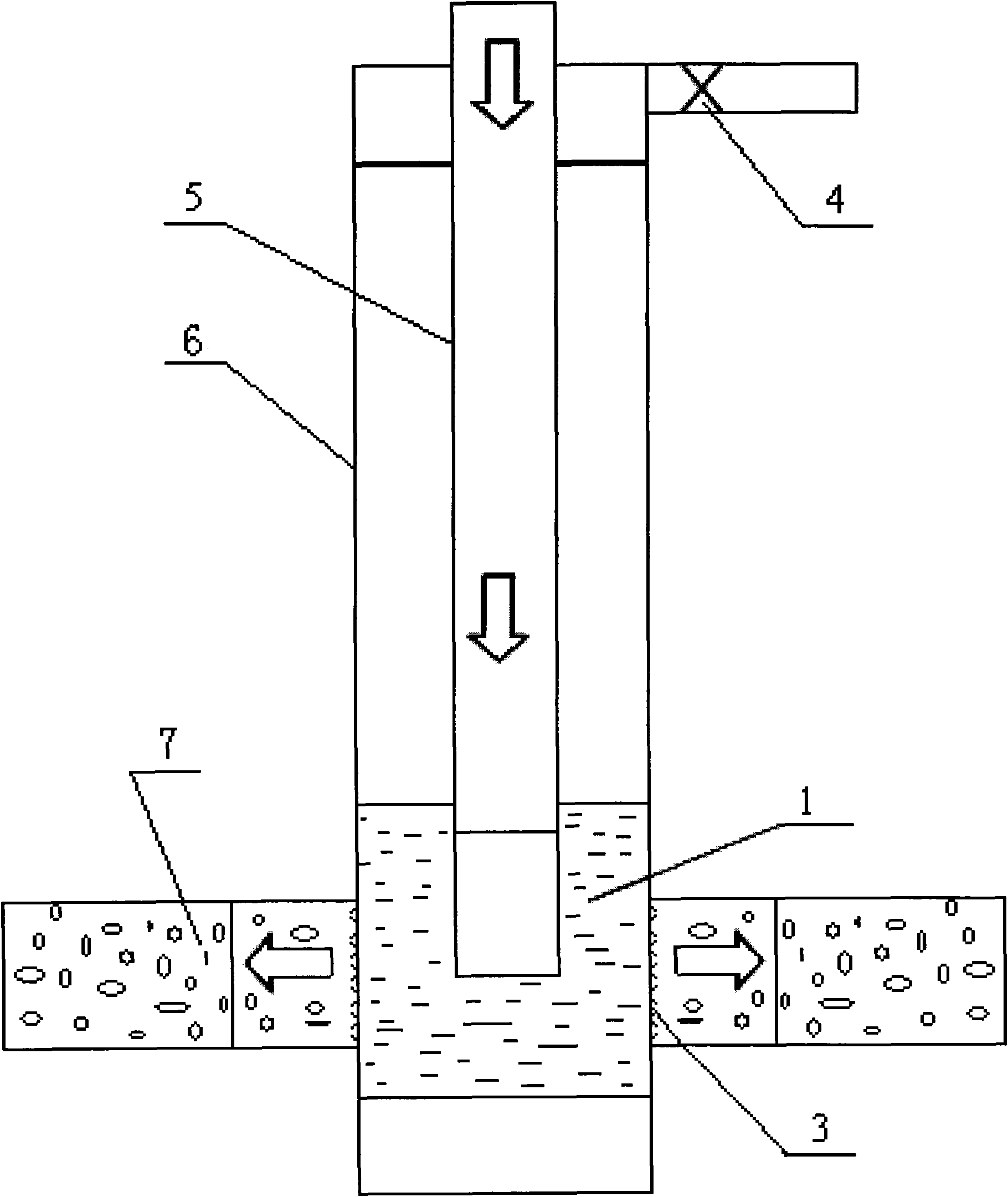
[0027] A. First carry out well drilling, refer to figure 2 . Connect the well gauge with an outer diameter of 118 mm to the lower end of the tubing 5 and run it into the casing 6, and use the well gauge to clean and shape the inner wall of the casing 6 in the whole well, so that the well gauge can pass through the casing 6 without hindrance .

[0028] B. Inject active water with surfactant and anti-swelling agent through oil pipe 5 to perform positive flushing operation on the inner wall of casing 6 to remove dirt in the wellbore;

[0029] C. Insert 6m into oil pipe 5 3 Acid solution 1, use acid solution 1 to replace active water in...


PUM


Abstract

The invention discloses a method for removing the blockage of an oil-water well through magnetic positioning pulse acidification, which is used for acidifying an oil well in an oil field. The method comprises the following steps of: clearing and reshaping a mine shaft with a drift size gauge, washing the mine shaft with active water, and substituting acidizing fluid for the active water in an oil pipe until the active water reaches the middle part of an oil layer; and lifting an oil outlet pipe, loading in a high-power pulse processing device, magnetically positioning a perforation interval of required measurement, checking data, starting the device to process, lifting the device to an interval needing to be processed to process again after meeting a design requirement, taking out the high-power pulse processing device after processing, loading a pump and completing the well after discharging liquid from a production well, and completing the well after loading a production oil pipe into a water injection well to backwash the water injection well. The method has the advantages that: the high-power pulse processing device can precisely position the perforation interval of the oil-water well; and after processing with the acidizing fluid during pulse processing, the processing radius and the processing efficiency of the acidizing fluid can be effectively guaranteed and blocking substances in ducts can be more effectively corroded.

Description

technical field [0001] The invention relates to the technical field of oil recovery in oil fields, in particular to oil well acidification and blocking removal construction, and is a method for positioning and removing plugs in oil-water well reservoirs in oil fields. Background technique [0002] At present, with the continuous development of oilfields, production well reservoirs will be clogged to varying degrees due to various reasons. Conventional plugging removal methods include acidification, deflagration fracturing, fracturing, etc. However, deflagration fracturing and fracturing have a relatively large impact on the reservoir. First, it is easy to cause artificial fractures to communicate with natural fractures and cause water channeling. Rapid water breakthrough in oil production wells; second, the stimulation action point cannot be accurately controlled, and it is difficult to achieve selective or uniform plugging removal, which is more difficult for profile stimul...

Claims


Application Information

Patent Timeline
Patent Type & Authority Applications(China)
IPC IPC(8): E21B43/26E21B43/27E21B47/09E21B47/092
Inventor 杨立华杨华徐永高李永长黎晓茸张涛郑力军马丽萍
Owner PETROCHINA CO LTD
Why Eureka
Try Eureka