Novel energy-saving refrigerating unit and working method thereof

A refrigerating unit and working method technology, applied in the direction of refrigerating machines, refrigerating components, refrigeration and liquefaction, etc., can solve the problems of reduced total liquid reaching the evaporator, insignificant energy saving effect, increased unit cost, etc., and achieve liquid supercooling Large, low-cost, simple-to-control effects

Inactive Publication Date: 2010-12-15
DALIAN SANYO COMPRESSOR
View PDF5 Cites 5 Cited by
  • Summary
  • Abstract
  • Description
  • Claims
  • Application Information

AI Technical Summary

Problems solved by technology

The first method is mostly used in small units where the unit is relatively close to the condenser, but the increase in the degree of subcooling is limited; although the second method can increase the degree of subcooling of the liquid, due to the consumption of a part of the liquid refrigerant, the reach The total amount of liquid in the evaporator is reduced, and the energy-saving effect is not obvious; although the realization of the third method has a good energy-saving effect, it requires an additional refrigeration unit, which will inevitably increase the cost of the unit

Method used


Image

  • Novel energy-saving refrigerating unit and working method thereof
  • Novel energy-saving refrigerating unit and working method thereof
  • Novel energy-saving refrigerating unit and working method thereof

Examples


Embodiment Construction

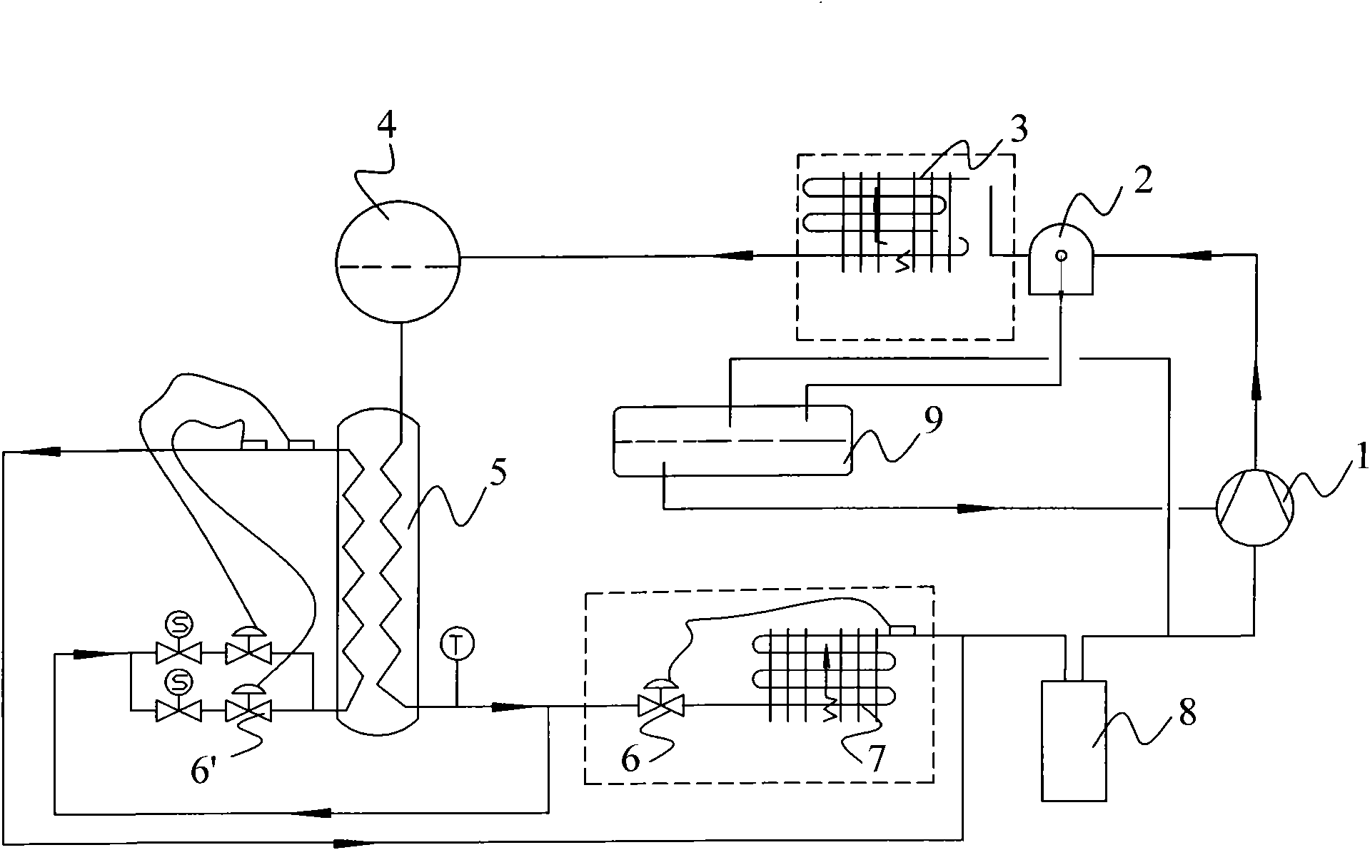
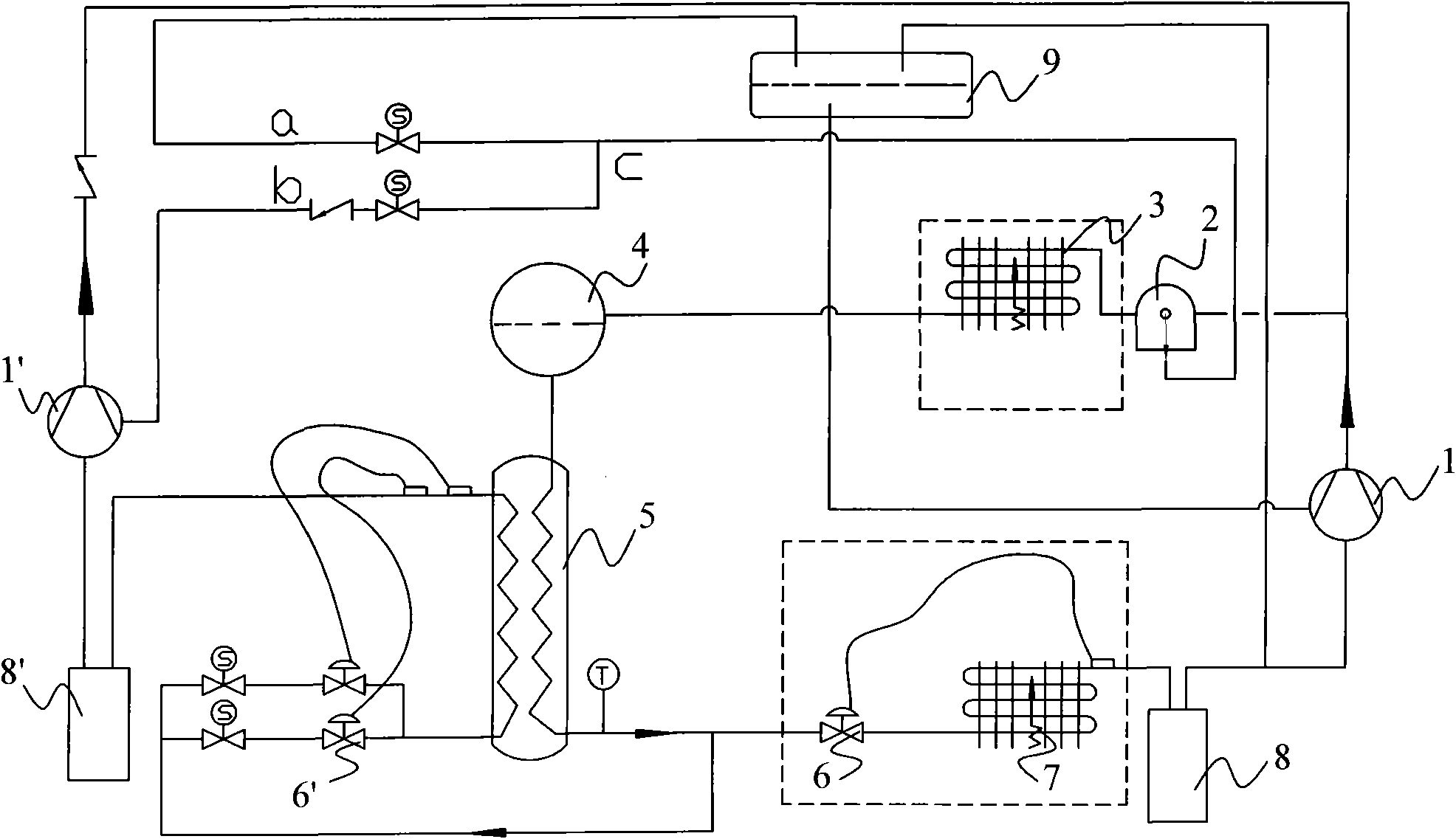
[0013] Such as figure 2 The new energy-saving refrigeration unit shown in the figure is connected by the outlet of the liquid receiver 4 to the inlet of the cooled end of the heat exchanger 5. The heat exchanger 5 is divided into two circuits by the outlet pipeline of the cooling terminal, and one pipeline passes through the medium temperature expansion valve. 6' and connected to the inlet of the low-pressure end of the heat exchanger 5, and the other path is connected to the low-temperature evaporator 7 through the low-temperature expansion valve 6, and the low-temperature evaporator 7 is connected to the gas-liquid separator 8. After being separated by the gas-liquid separator 8 Refrigerant gas enters the low-temperature compressor 1; the exhaust refrigerant outlet of the heat exchanger 5 is connected to the medium-temperature compressor 1' after passing through the medium-temperature gas-liquid separator 8', and the medium-temperature compressor 1' The exhaust pipe of the ...


PUM


Abstract

The invention discloses a novel energy-saving refrigerating unit and a working method thereof. In the novel energy-saving refrigerating unit, liquid from a condenser enters a liquid receiver; the high-pressure liquid coming out of the liquid receiver is divided into two paths by a heat exchanger; one path of the liquid is throttled by an expansion valve and enters the low-pressure end of the heat exchanger to be evaporated; the other path of the liquid enters a low-temperature evaporator through the low-temperature expansion valve, and a refrigerant gas returns to a gas-liquid separator of the unit and enters a low-temperature compressor to be compressed; the gas evaporated by the heat exchanger enters a moderate-temperature gas-liquid separator and a moderate-temperature compressor to be compressed; the exhaust gas of the moderate-temperature compressor is mixed with the exhaust gas of the low-temperature compressor by a check valve, and the mixed exhaust gas enters an oil separator and then flows into the condenser and returns to the liquid receiver; the refrigerant oil separated by the oil separator enters an oil receiver; and when the moderate-temperature compressor is short of oil, the refrigerant oil in the oil content stops entering the oil receiver and starts to enter the moderate-temperature compressor. The novel energy-saving refrigerating unit fulfills the purpose of saving energy for the unit by using the cold energy of the highly efficient moderate-temperature compressor in the unit.

Description

technical field [0001] The invention relates to a novel energy-saving refrigeration unit and a control method thereof. Background technique [0002] When the evaporator is far away from the low-temperature unit or at a high position, in order to reduce the cooling capacity reduction caused by resistance in the tube and gravity, increasing the subcooling degree of the refrigerant is a common and effective way. There are three common ways for the unit to achieve liquid supercooling: 1. The liquid from the liquid receiver passes through the subcooling section set at the lower part of the condenser, and uses air to provide supercooling for the refrigerant liquid; 2. Use part of the liquid in the unit itself Provides subcooling for another part of the liquid ( figure 1 ) The outlet liquid of the liquid receiver is divided into two paths, one of which passes through the expansion valve to cool the other path of liquid, the supercooled liquid enters the cold end and then evaporate...

Claims


Application Information

Patent Timeline
Patent Type & Authority Applications(China)
IPC IPC(8): F25B1/00F25B31/00
Inventor 孟庆海秦海杰单永明
Owner DALIAN SANYO COMPRESSOR
Why Eureka
Try Eureka