Method for measuring geogrid deformation and stress by utilizing fiber bragg grating

A technology of geogrid and optical fiber grating, which is applied in the measurement of the change force of the optical properties of the material when it is stressed, the measurement device, the use of optical devices, etc., can solve the lack of measurement means, the inaccurate quantitative evaluation, and the measurement results Error and other problems, to achieve the effect of accurate measurement, high cost performance, and satisfactory measurement accuracy

Inactive Publication Date: 2010-12-15
NANJING HYDRAULIC RES INST
View PDF5 Cites 24 Cited by
  • Summary
  • Abstract
  • Description
  • Claims
  • Application Information

AI Technical Summary

Problems solved by technology

[0002] At present, geogrids are widely used in soil reinforcement work in civil engineering, water conservancy, electric power, transportation and other projects, but the function of geogrids in soil reinforcement cannot be accurately quantified due to the lack of effective measurement methods Therefore, the design of geogrid in soil reinforcement can only be designed according to relevant regulations and specifications using empirical methods. In the past, measurement methods such as strain gauges were used to try to measure the

Method used


Image

  • Method for measuring geogrid deformation and stress by utilizing fiber bragg grating
  • Method for measuring geogrid deformation and stress by utilizing fiber bragg grating
  • Method for measuring geogrid deformation and stress by utilizing fiber bragg grating

Examples


Example Embodiment

[0025] Example 1:

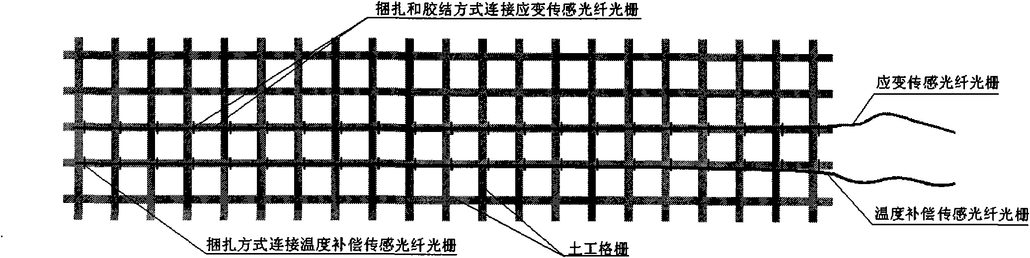
[0026] like figure 1 , figure 2 and image 3 As shown, the method for measuring geogrid deformation and stress by using fiber grating includes the following steps:

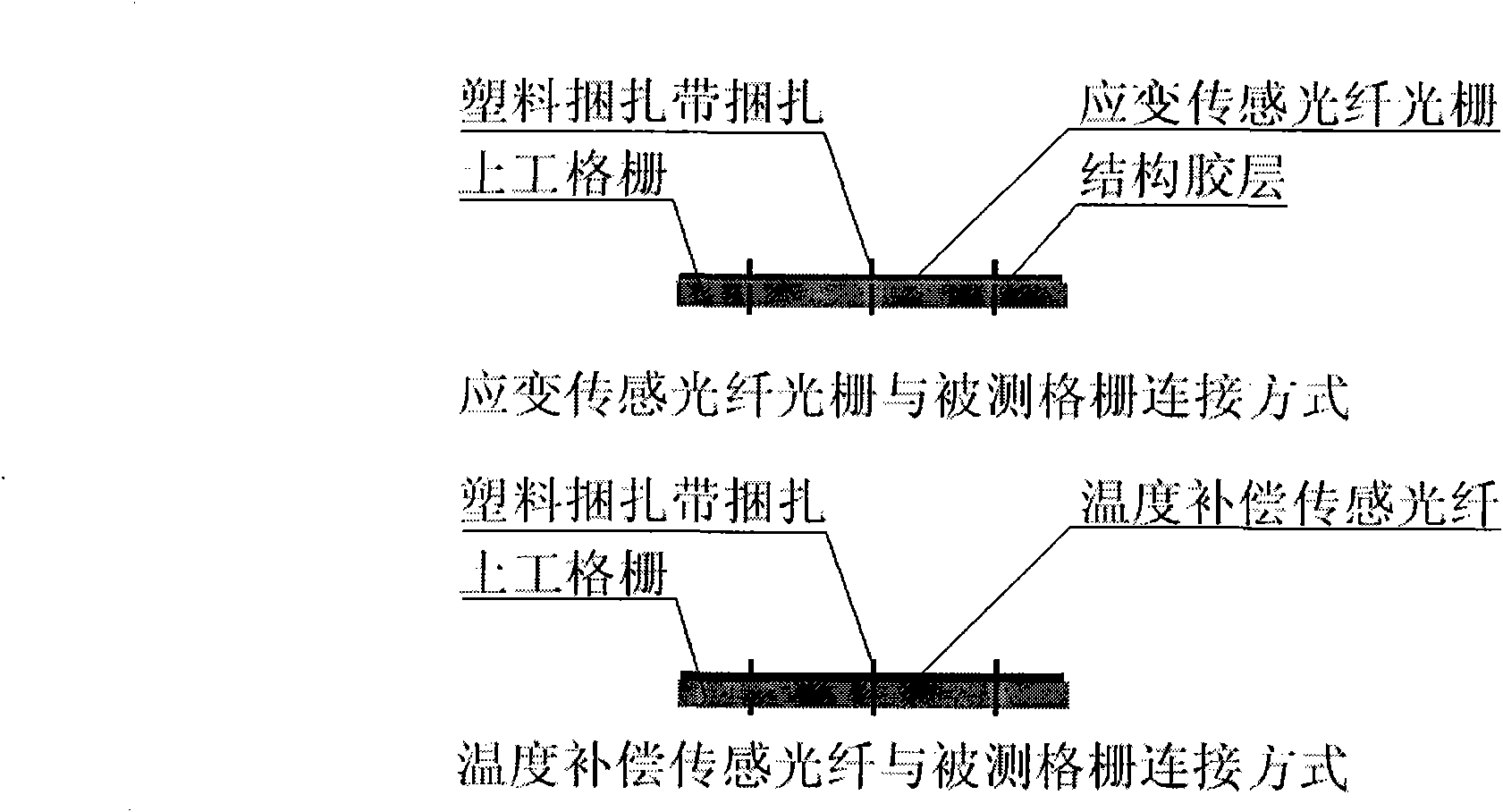
[0027] 1) After the geogrid is laid on the project site, clean the surface of the grid at the position of the grid to be tested, lay strain and temperature compensation sensing fibers on the grid to be tested, and bind the sensing fibers to the grid with plastic strapping tape. On the surface, after the strain sensing optical fiber is bundled, the structural glue is applied to the optical fiber and the foundation surface of the geogrid to make the two tightly bonded as a whole, so as to ensure that the deformation of the two is consistent, such as figure 1 and figure 2 ;

[0028] 2) The sensing optical fiber is led out from one end and connected to the optical fiber jumper connector to prepare for entering the distributed optical fiber measurement system;

[0029] 3) Connect the jumper ...

Example Embodiment

[0030] Example 2:

[0031] It is basically the same as Embodiment 1, except that the sensing optical fiber and the geogrid are bundled and cemented indoors and then transported to the site for laying of the geogrid.

Example Embodiment

[0032] Example 3:

[0033] It is basically the same as Embodiment 1, except that the sensing optical fiber is first implanted into the glass fiber geogrid and then transported to the site for laying of the geogrid.


PUM

PropertyMeasurementUnit
Diameteraaaaaaaaaa

Abstract

The invention discloses a method for measuring geogrid deformation and stress by utilizing a fiber bragg grating, comprising the following steps: connecting a strain fiber and a sensing fiber with longitude gate or latitude gate of the measured geogrid by adopting a structural adhesive and a banding manner; laying a temperature compensation sensing fiber on the adjacent longitude gates or latitude gates of the measured geogrid; manufacturing a sensing fiber armoring structure; packing geogrid longitude gate or latitude gate laid with sensing fibers by adopting adhesive tapes after the laying of sensing fibers on the measured geogrid is finished; laying and installing the geogrid which is laid with sensing fibers and finishes protection structure in place; one end of sensing fiber bragg grating leads out and is connected with a fiber optic jumper joint to enter into a distributed fiber measuring system. The method of the invention is simple and easily operated, has low cost and can accurately measure the deformation and stress of the geogrid, and the measuring precision can satisfy project actual measuring demands.

Description

technical field [0001] The invention relates to a kind of deformation and force monitoring of geogrid used in soil reinforcement work of civil engineering, water conservancy, electric power, transportation and other projects, especially relates to a method of using optical fiber grating to measure the deformation and force of geogrid Methods. Background technique [0002] At present, geogrids are widely used in soil reinforcement work in civil engineering, water conservancy, electric power, transportation and other projects, but the function of geogrids in soil reinforcement cannot be accurately quantified due to the lack of effective measurement methods Therefore, the design of geogrid in soil reinforcement can only be designed according to relevant regulations and specifications using empirical methods. In the past, measurement methods such as strain gauges were used to try to measure the deformation of reinforced geogrid in soil. However, due to the rigidity of the monit...

Claims


Application Information

Patent Timeline
IPC IPC(8): G01B11/16G01L1/24
Inventor 何宁汪璋淳丁勇何斌钱亚俊王国利郑澄峰钟祥海
Owner NANJING HYDRAULIC RES INST
Why Eureka
Try Eureka