Method for measuring phase difference of common-period signals based on delay unit dedicated for FPGA

A technology of periodic signal and measurement method, applied in the direction of phase angle between voltage and current, measurement device, measurement of electrical variables, etc., can solve the problems of high filling pulse signal frequency, large measurement error, and low measurement accuracy, and achieve high precision The effect of high, short development cycle and simple structure

Inactive Publication Date: 2010-12-15
XIDIAN UNIV
View PDF2 Cites 24 Cited by
  • Summary
  • Abstract
  • Description
  • Claims
  • Application Information

AI Technical Summary

Problems solved by technology

The first three are all calculated from the numerical value of the sampled signal, and the measurement error is relatively large
And like other methods based on pulse filling, not only requires a high frequency of filling pulse signal, but also the measurement accuracy is not high

Method used


Image

  • Method for measuring phase difference of common-period signals based on delay unit dedicated for FPGA
  • Method for measuring phase difference of common-period signals based on delay unit dedicated for FPGA
  • Method for measuring phase difference of common-period signals based on delay unit dedicated for FPGA

Examples


Embodiment Construction

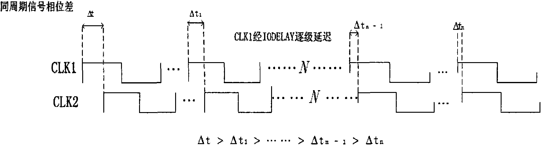
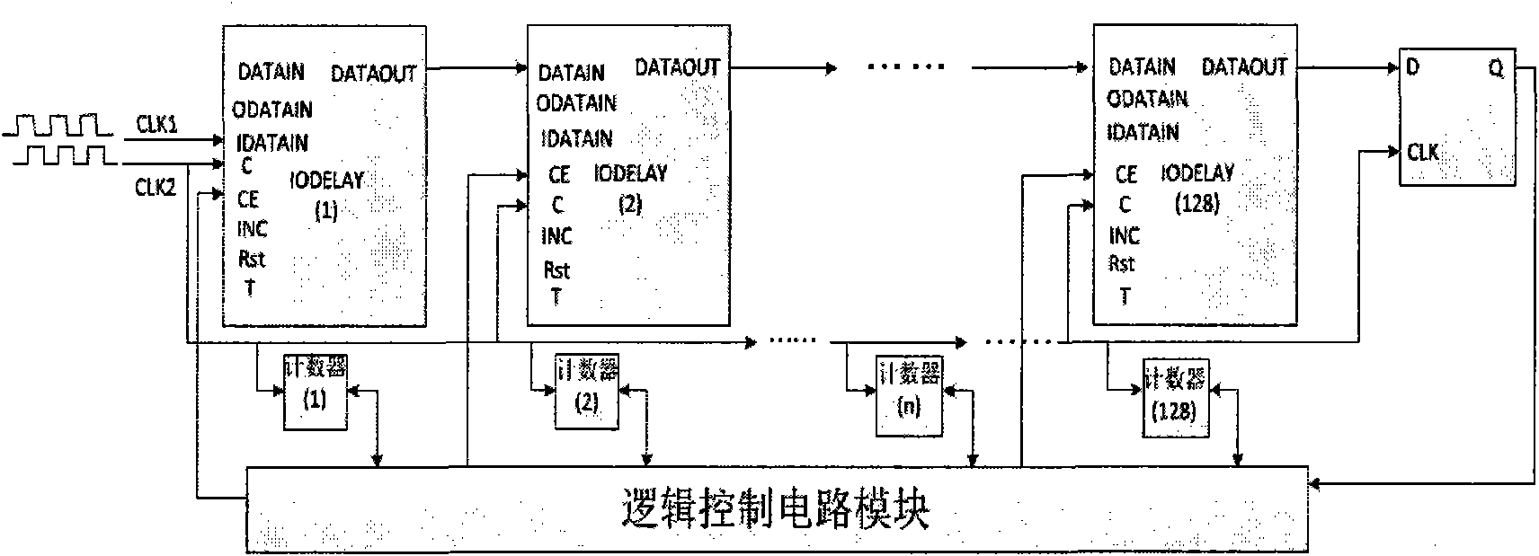
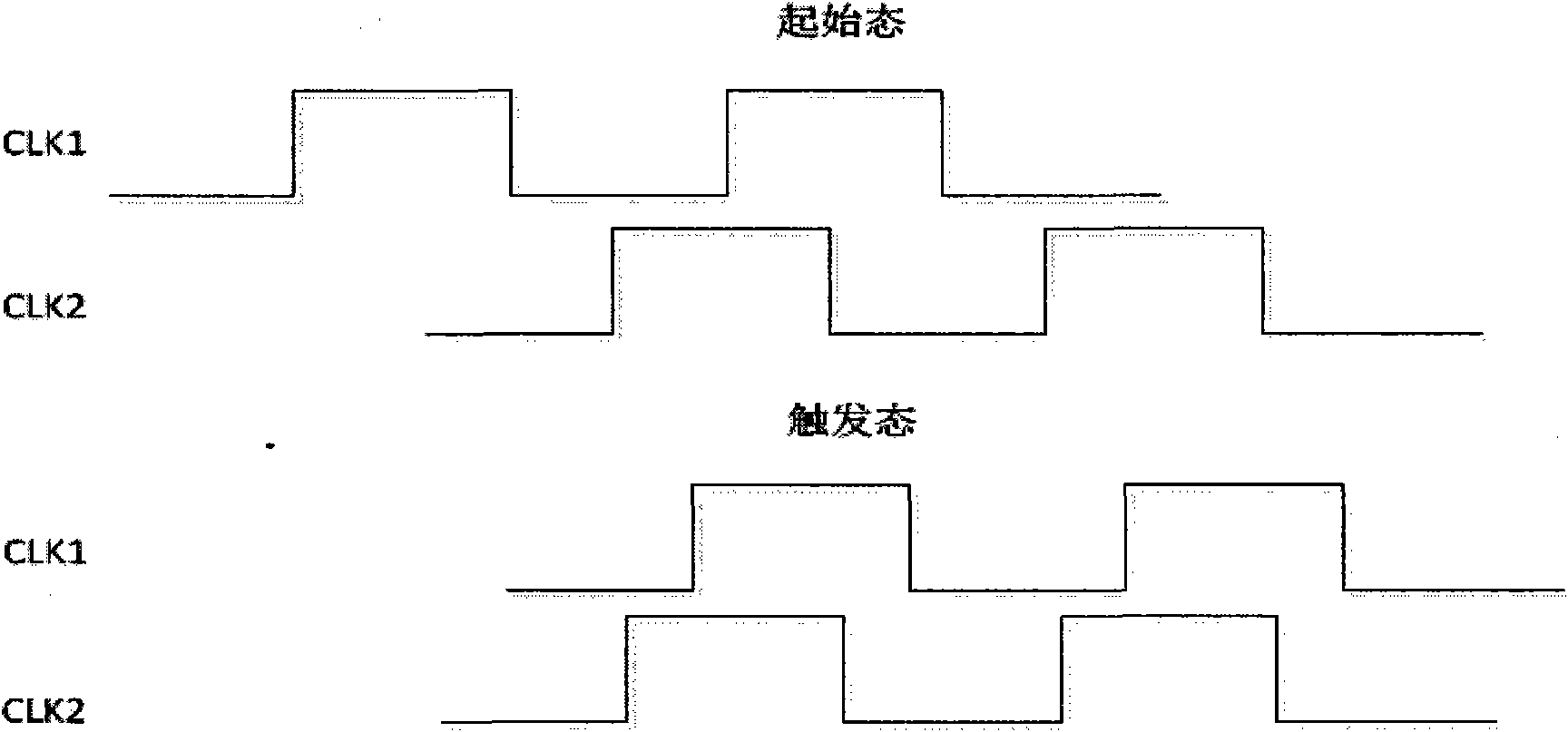
[0018] The invention proposes a Xilinx FPGA-based method for measuring the phase difference of the same period signal with high precision. The measurement method that the present invention adopts is to utilize the tap line of IODELAY, CLK1 is carried out accurate delay, and the D end of input D flip-flop; CLK2 is input to the CLK end of D flip-flop and the CLK end of counter by the global clock network of FPGA; The D flip-flop outputs the change of the Q terminal value, detects the edge coincidence information of the delayed CLK1 and CLK2, and triggers the logic control circuit, so as to control and calculate the phase difference of the same cycle signal.

[0019] Xilinx Virtex-4 and Virtex-5 FPGA devices have a programmable input and output delay unit IODELAY in each IOB. IODELAY is a variable 64-bit delay chain. When used in conjunction with IDELAYCTRL, IODELAY can provide a precise time-delta delay that is not affected by process, temperature, or voltage variations. Each ...


PUM


Abstract

The invention discloses a circuit for measuring phase difference of common-period signals, which comprises 128 IODELAYs (programmable input and output delay units dedicated for Xilinx FPGA), a D trigger, 128 6-digital counters, a logic control circuit and two paths of common-period signals to be measured: the first path of period signals CLK1 and the second path of period signals CLK2. The method provides a method for measuring the phase difference of the common-period signals in high accuracy, which comprises the following steps: the CLK1 is sent to input ends of the IODELAYs and input to a D end of the D trigger after step-by-step delay by the IODELAYs; the CLK2 is input to a CLK end of the D trigger and CLK ends of the counters through a global clock network; and variation of a Q value at an output end of the D trigger is detected, thus obtaining edge coincidence information of the CLK1 and the CLK2 after the delay and achieving the aim of measuring the phase difference of the common-period signals according to the delay amount of the IODELAYs.

Description

Technical field: [0001] The invention relates to a method for measuring the phase difference of the same periodic signal, that is, a method for measuring the phase difference of the same periodic signal with high precision using Xilinx FPGA as the hardware platform and using Verilog HDL and Xilinx FPGA primitives as the hardware description language. Background technique: [0002] In the field of modern signal measurement, it is extremely important in engineering to measure the frequency, period and phase difference of two signals with the same period. High-precision phase difference measurement technology of the same period signal, especially the measurement technology of picosecond level is extremely important. In recent years, frequency cycle measurement has begun to develop towards digitalization, such as using FPGA devices, etc. The advantages lie in simple hardware, strong adaptability and high precision. In engineering practice, it is mainly used in time synchronizat...

Claims


Application Information

Patent Timeline
Patent Type & Authority Applications(China)
IPC IPC(8): G01R25/00
Inventor 王海姚秦刘杰王俭曾宪雄张敏范慧娟
Owner XIDIAN UNIV
Why Eureka
Try Eureka