
Broadband directional antenna for mobile communication

A directional antenna and mobile communication technology, applied in the antenna grounding device, radiating element structure and other directions, can solve the problems of inconvenient miniaturization design, high antenna gain, and high processing cost, and achieve convenient miniaturization design, high gain, and flexible design. Effect

Inactive Publication Date: 2010-12-15
JIANGSU ANTENAI TECH
View PDF6 Cites 3 Cited by
  • Summary
  • Abstract
  • Description
  • Claims
  • Application Information

AI Technical Summary

Problems solved by technology

At the same time, solve some shortcomings of existing antennas: (1) At present, the gain of the antenna is required to be relatively high, such as a gain of 6-7dBi is required, and most of the existing antennas are Yagi antennas or logarithmic periodic antennas. increase, its volume increases, so it is not convenient for miniaturization design
Moreover, most of the developed products are complex in structure, cumbersome in design, poor in versatility, high in processing cost, and have certain defects in performance, so they are not suitable for promotion. This mobile communication cell coverage has caused certain difficulties, so the development of multi-band, miniaturization, and simple structure, The design of flexible and low-cost directional antenna is one of the current research hotspots

Method used


Image

  • Broadband directional antenna for mobile communication
  • Broadband directional antenna for mobile communication
  • Broadband directional antenna for mobile communication

Examples


Embodiment Construction

[0014] The present invention will be described in further detail below in conjunction with the accompanying drawings and specific embodiments.

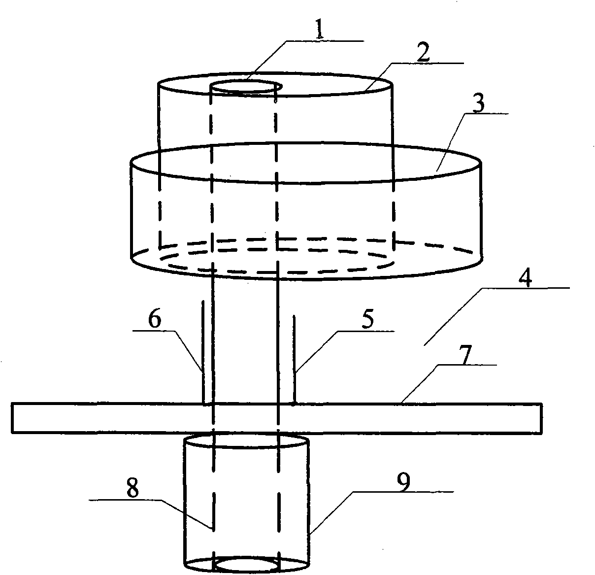
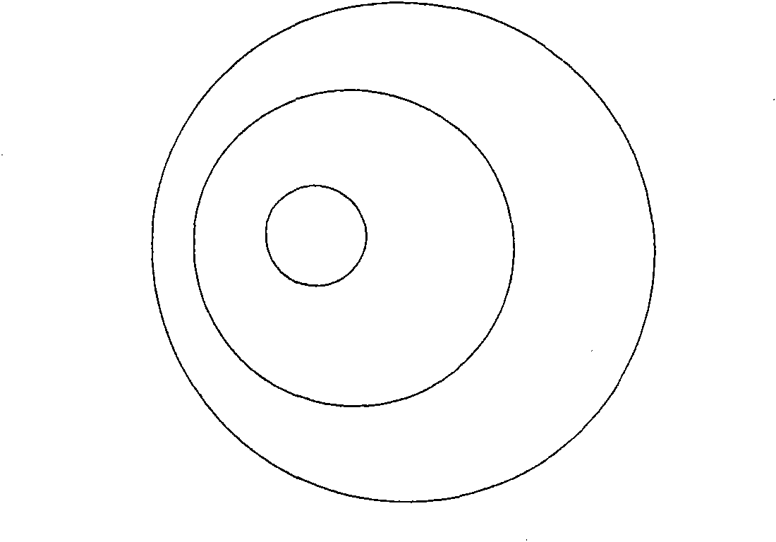
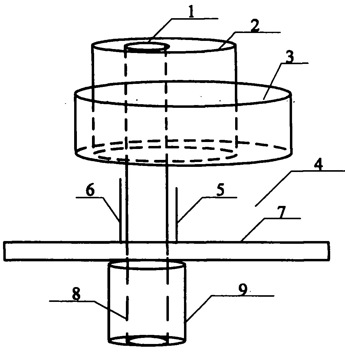
[0015] like figure 1 , figure 2 As shown, 1 is the feeding probe, 2 is the small circular vertical patch radiation unit, 3 is the large circular vertical patch radiation unit, 4 is the supporting medium, 5 is the small compensation sheet, 6 is the large compensation sheet, 7 is the grounding plate, 8 is the inner conductor of the main feeder line, and 9 is the main feeder line.

[0016] A broadband directional antenna for mobile communication includes a ground plate 7, a small circular vertical patch radiating unit 2, a large circular vertical patch radiating unit 3, a feeding probe 1, a supporting medium 4, and a small compensation sheet 5 , Large compensation piece 6, feed structure.

[0017] The main radiating unit part of the antenna is composed of two non-concentric circular vertical patches (ie, the small circular vertical p...


PUM


Abstract

The invention relates to a broadband directional antenna for mobile communication. A primary radiating element part of the antenna consists of a small ring-shaped vertical patch radiating element (2) and a big ring-shaped vertical patch radiating element (3) which are eccentrically arranged, wherein the small ring-shaped vertical patch radiating element (2) is higher than the big ring-shaped vertical patch radiating element (3); a feed probe (1) is arranged in the small ring-shaped vertical patch radiating element (2) and is flush with the small ring-shaped vertical patch radiating element (2); a small compensating plate (5) and a big compensating plate (6) are arranged at the periphery of the feed probe (1) on a ground plane of the antenna; an outer conductor of a main feeder line (9) isdirectly welded with a ground plate (7); a conductor (8) in the main feeder line is connected with the feed probe (1); and a supporting medium (4) is arranged between the primary radiating element ofthe antenna and the ground plate (7).

Description

technical field [0001] The invention relates to a directional antenna, in particular to a broadband directional antenna for mobile communication. Background technique [0002] As radio communication equipment and electronic information equipment are developing toward multi-functionality, miniaturization, ultra-wideband and friendly coordination with the surrounding environment, this makes broadband and miniaturization one of the hot research topics at home and abroad. It involves the broadband impedance matching technology of the antenna, the loading technology of the antenna, the reactance compensation technology of the antenna, the optimized design of the small antenna shape and other advanced technologies and processes. At the same time, solve some shortcomings of existing antennas: (1) At present, the gain of the antenna is required to be relatively high, such as a gain of 6-7dBi is required, and most of the existing antennas are Yagi antennas or logarithmic periodic ant...

Claims


Application Information

Patent Timeline
Patent Type & Authority Applications(China)
IPC IPC(8): H01Q1/36H01Q1/48
Inventor 邢红兵徐燕李迎松刘乘源姜兴文吴成云王积祥
Owner JIANGSU ANTENAI TECH
Learn More