Hydraulic motor glue wheel-supported stepless transmission drum mixer

A cylinder mixing and hydraulic motor technology, applied in mixers, mixers with rotating containers, dissolving, etc., can solve the problems of fast wear of idler rollers, high power of motors, and insufficient supporting force of rubber wheels, etc., to achieve material mixing and The effect of uniform granulation, large load bearing capacity and small starting resistance

Inactive Publication Date: 2012-06-13
YANSHAN UNIV
View PDF5 Cites 0 Cited by
  • Summary
  • Abstract
  • Description
  • Claims
  • Application Information

AI Technical Summary

Problems solved by technology

Some use frequency converters to realize the speed regulation of the cylinder, but this method requires a large motor power and a high-voltage power supply, which is expensive and unstable
At the same time, due to the large volume of the motor reducer required to provide power for the large cylinder mixer, the motor reducer occupies the axial space of the cylinder and the rubber wheels cannot be evenly arranged, resulting in insufficient supporting force of the rubber wheels and premature wear. Therefore, all large-scale cylindrical mixers adopt the structure of metal roller supporting ring gear transmission. This results in serious vibration, and the roller wears quickly and cannot be repaired.

Method used


Image

  • Hydraulic motor glue wheel-supported stepless transmission drum mixer
  • Hydraulic motor glue wheel-supported stepless transmission drum mixer
  • Hydraulic motor glue wheel-supported stepless transmission drum mixer

Examples


Embodiment 1

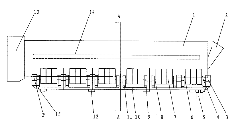
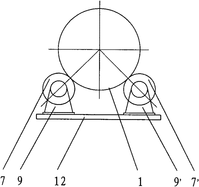
[0021] figure 1 It is the cylinder mixer with stepless transmission supported by the rubber wheels of the first hydraulic motor disclosed in the present invention. The cylinder body 1 of the cylinder mixer is provided with two sets of rubber wheel driving groups at radially symmetrical positions on both sides. The rubber wheels The transmission group is composed of the first hydraulic motor 3, the driving main shaft 6, the first rubber wheel group 7, the self-aligning bearing 8, the first bearing seat and the bracket 9, and three sets of the first rubber wheel group 7 are installed on the driving main shaft 6, each group The first rubber wheel group 7 is equipped with 3 tires. The driving main shaft 6 is installed in the shaft hole of the self-aligning bearing 8 of the first bearing seat and the bracket 9, the driving main shaft 6 is connected with the output shaft of the first hydraulic motor 3 through the shaft coupling 4, and the first hydraulic motor 3 drives the main sha...

Embodiment 2

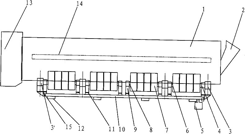
[0023] image 3 It is a cylindrical mixer with stepless transmission supported by rubber wheels of the second hydraulic motor disclosed in the present invention. The cylinder body 1 of the cylindrical mixer is driven by two sets of rubber wheel driving groups located at radially symmetrical positions on both sides of the cylindrical mixer. 2 groups of first rubber wheel groups 7 are installed on the main shaft 6, and every assembly has 4 tires. Others are the same as in Example 1.

Embodiment 3

[0025] Figure 4 It is the third hydraulic motor rubber wheel supported stepless transmission cylinder mixer disclosed in the present invention. The cylinder body 1 of the cylinder mixer is driven by two sets of rubber wheel driving groups located at radially symmetrical positions on both sides of the cylinder mixer. 3 groups of first rubber wheel groups 7 are installed on the main shaft 6, wherein 2 are assembled with 4 tires, and the other is assembled with 2 tires. Others are the same as in Example 1.


PUM


Abstract

The invention discloses a hydraulic motor glue wheel-supported stepless transmission drum mixer. A drum body (1) of the drum mixer is driven by glue wheel driving groups which are radially and symmetrically arranged on one side or two sides of the drum body; a driving main shaft (6) is arranged in the shaft hole of a self-aligning bearing (8) of a first bearing seat and a bracket (9) and providedwith 1 to 3 first glue wheel groups (7); the output shaft of a first hydraulic motor (3) is coupled with the driving main shaft (6) through a coupling (4); a frame (10) is provided with the first bearing seat and the bracket (9); a damping glue cushion (11) is arranged between the base of the frame and the frame (10); and the frame (10) is fixed on a rigid foundation (12). The hydraulic motor glue wheel-supported stepless transmission drum mixer can obviously reduce the vibration caused by the drum body during rotation and impact force caused by feeding and has the advantages of stable operation, low noise, small starting resistance, strong load bearing ability, simple structure, convenient maintenance and the like.

Description

technical field [0001] The invention relates to a primary and secondary cylinder mixer for mixing sintered materials. technical background [0002] Before the mineral powder is sintered, the mixture needs to be mixed through a cylinder mixer for primary and secondary mixing, so that the material temperature, moisture and components of the mixture can be mixed evenly and granulated. Due to the different composition of the mixture, the mixing and granulation is completed in the primary and secondary mixers respectively, so the required speed of the mixer is also different, and the speed needs to be determined with the best mixing effect and the highest output. The rotation of the existing cylinder mixer is driven by the transmission pinion to rotate the large ring gear on the cylinder, or the transmission rubber wheel supporting the cylinder is driven by the motor reducer to rotate the cylinder. changing. Some adopt frequency converter to realize cylinder speed regulation, b...

Claims


Application Information

Patent Timeline
Patent Type & Authority Patents(China)
IPC IPC(8): B01F9/02B01F29/60
Inventor 白明华何云华郑海武
Owner YANSHAN UNIV
Why Eureka
Try Eureka