
Anti-sniper laser active detection system and method

An active detection and laser technology, applied in radio wave measurement system, measurement device, electromagnetic wave re-radiation and other directions, can solve the problem that there is no compass to locate the rangefinder to measure the target, no sniper dazzling interference, inability to distinguish the sniper scope and Ordinary reflective targets and other problems, to achieve the effect of simple structure, strong function and large field of view

Active Publication Date: 2010-12-22
CHANGCHUN ZEAN TECH
View PDF6 Cites 22 Cited by
  • Summary
  • Abstract
  • Description
  • Claims
  • Application Information

AI Technical Summary

Problems solved by technology

Since the device uses a photoelectric detector for echo detection and cannot be combined with image analysis, it can only be judged according to the strength of the echo signal, and cannot distinguish between sniper sights and ordinary reflective targets, which is greatly limited in application.
In addition, even if the device finds the target, it can only provide prompts and alarms, and cannot immediately dazzle the sniper, and it does not have its own GPS, compass positioning, and range finder to measure targets.

Method used


Image

  • Anti-sniper laser active detection system and method
  • Anti-sniper laser active detection system and method
  • Anti-sniper laser active detection system and method

Examples


Embodiment Construction

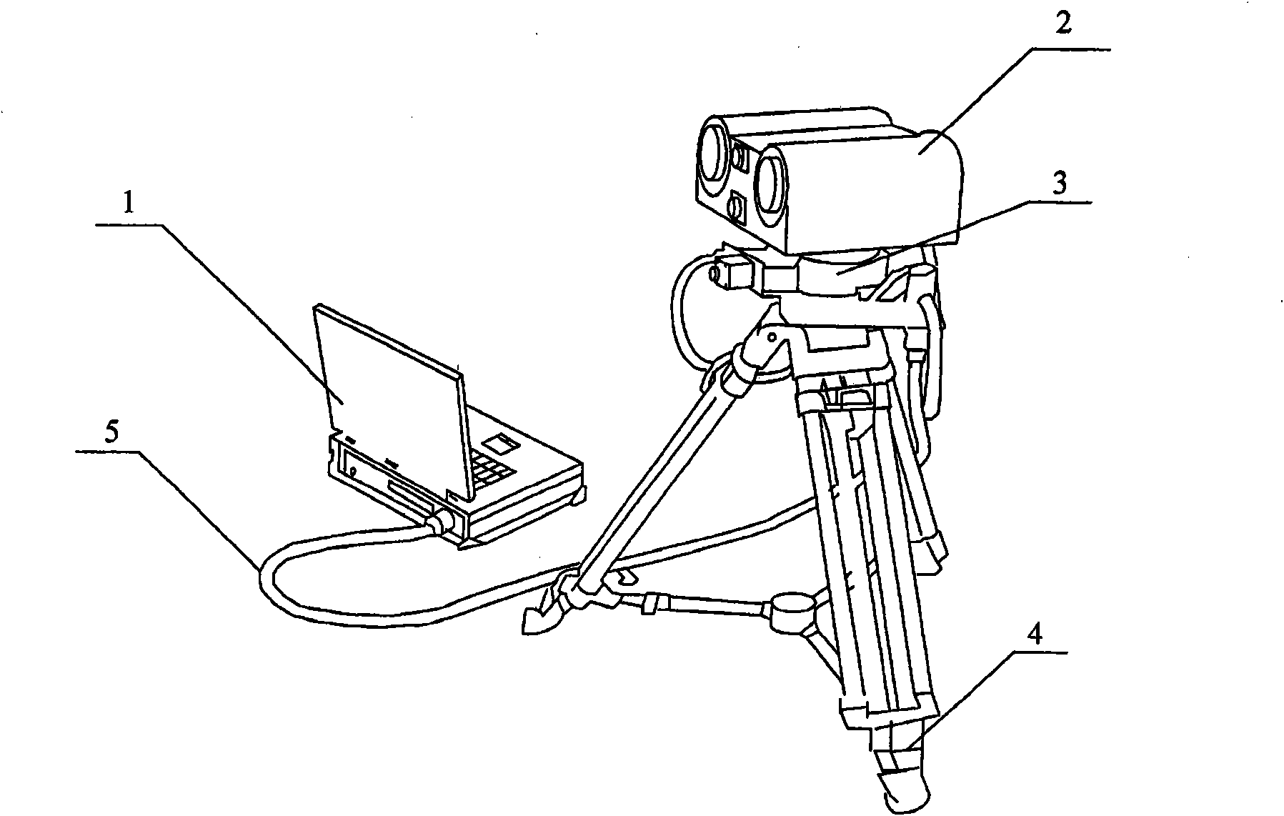
[0034] Such as figure 1 As shown, the system consists of a portable industrial computer 1, an anti-sniper detection head 2, a two-dimensional turntable 3, a support tripod 4, and an aviation plug connection 5. The portable industrial computer 1 and the anti-sniper detection head 2 are connected through the aerial plug connection 5, the anti-sniper detection head 2 is fixed on the two-dimensional turntable 3, and the two-dimensional turntable 3 is fixed on the support tripod 4. When the two-dimensional turntable 3 moves horizontally, it will drive the anti-sniper detection head 2 to scan horizontally; when the two-dimensional turntable 3 moves in pitch, it will drive the anti-sniper detection head 2 to scan vertically.

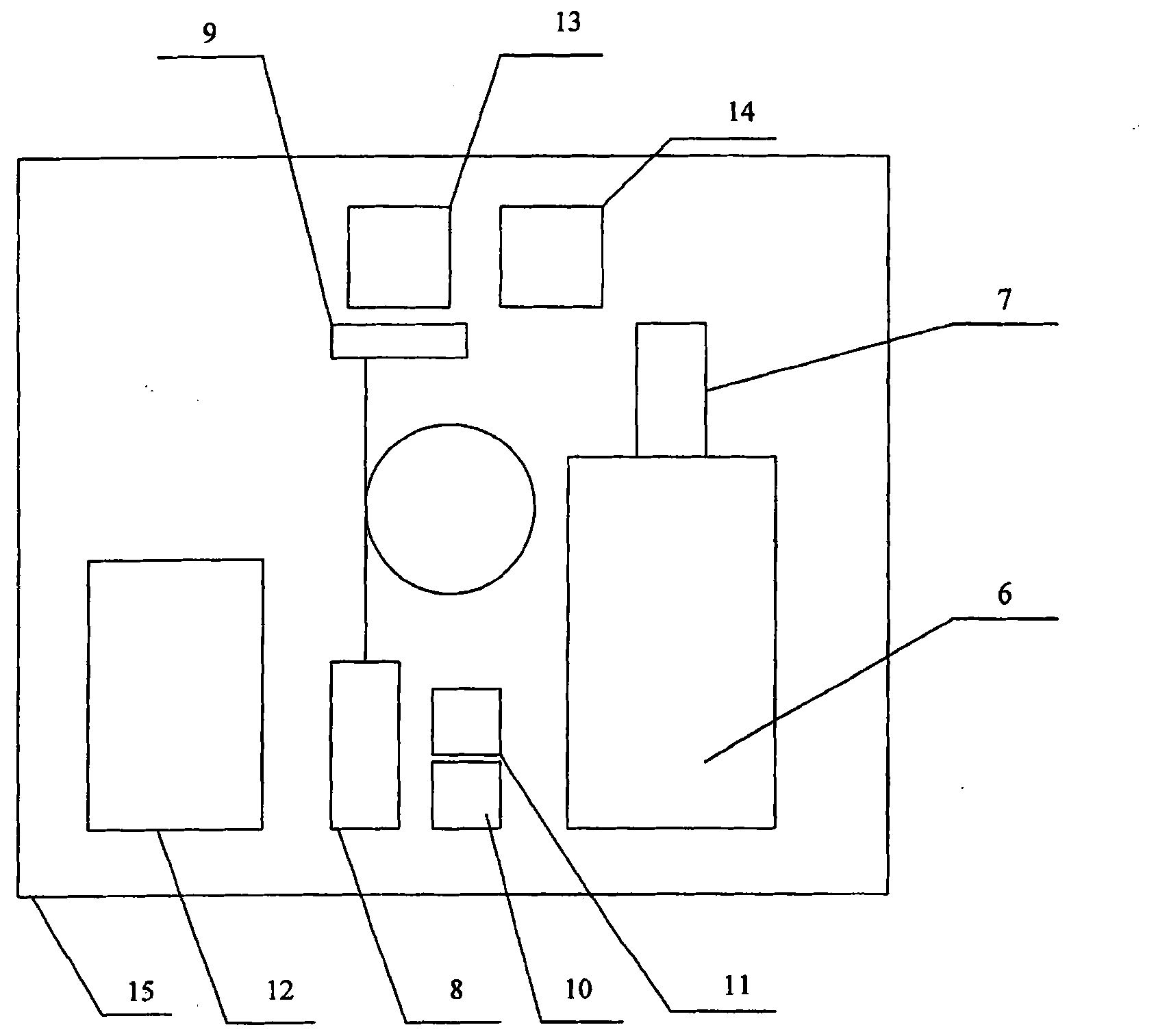
[0035] Such as figure 2 As shown, the anti-sniper detection head includes: a zoom lens 6, an image sensor 7, a transmitting antenna 8 of an infrared laser, an infrared laser 9, a transmitting antenna 10 of a dazzling laser, a dazzling laser 11, a distance mea...


PUM


Abstract

The invention discloses an anti-sniper laser active detection system, which comprises an anti-sniper detector head and a portable industrial personal computer and is characterized in that the anti-sniper detector head is used for emitting infrared detection laser and glaring laser, receiving reflected laser echo signals, obtaining target images, measuring target distance and positioning the coordinates of a detected target; and the portable industrial personal computer is used for controlling the emission of the infrared detection laser and the glaring laser, carrying out the automatic identification, processing and storage on image signals fed back by the anti-sniper detector head, and supplying power for the system. The invention has simple structure and is convenient to carry. The system has large detection visual angle, automatically identifies suspicious target, and gives an alarm for prompting when finding the target by adopting an image processing method; the system can rapidlyposition and look into the position and the distance of an optical lend target, provide day and night amplified observation for an observation field for recording and shooting, and have an recognition rate far higher than the recognition rate of a working method with a unit detector; and the system further can carry out the coordinate positioning and the glaring suppression on the target. The invention provides the system and the method with powerful function and better practicability for various military necessities, such as the protection of very important person, field operations of anti-sniper army, anti-sniper operation and the like.

Description

technical field [0001] The invention relates to an anti-sniper laser active detection system and method. Background technique [0002] Sniping and counter-sniping have always been a pair of contradictions that ebb and flow. In order to deal with the huge casualties and panic caused by sniping, countries have not only strengthened research on anti-sniper tactics, but also launched various types of "anti-sniper weapons" on the technical level. detection system” to improve the technical capability of anti-sniping. However, most of the molded products are passive detection. Although the position of the sniper can be accurately found, it can only be found after the sniper fires the first shot. This can only be a method of remedying the situation. [0003] In addition, the utility model patent application document with the publication number CN201100838 discloses an anti-sniper detector, which includes a laser emitting unit and a unit laser receiving part. In this technical solut...

Claims


Application Information

Patent Timeline
Patent Type & Authority Applications(China)
IPC IPC(8): F41H11/00G01S17/89
Inventor 于洪波胡永宏
Owner CHANGCHUN ZEAN TECH
Learn More