Grid-control bridge rectifier with surge current limiter

A bridge rectifier, inrush current technology, applied in emergency protection circuit devices for limiting overcurrent/overvoltage, AC power input conversion to DC power output, electrical components, etc., can solve the loss of inrush current limiter And other issues

Inactive Publication Date: 2010-12-22
GLACIALTECH +1
View PDF1 Cites 6 Cited by
  • Summary
  • Abstract
  • Description
  • Claims
  • Application Information

AI Technical Summary

Problems solved by technology

Despite the simple structure and cheap price, the forward voltage drop of the rectifier diode makes the diode bridge rectifier suffer from high conduction loss in high current applications; the negative temperature coefficient of the thermistor (negative temperature coefficient) makes the thermistor almost lose the function of inrush current limiter at high temperature

Method used


Image

  • Grid-control bridge rectifier with surge current limiter
  • Grid-control bridge rectifier with surge current limiter
  • Grid-control bridge rectifier with surge current limiter

Examples


Embodiment Construction

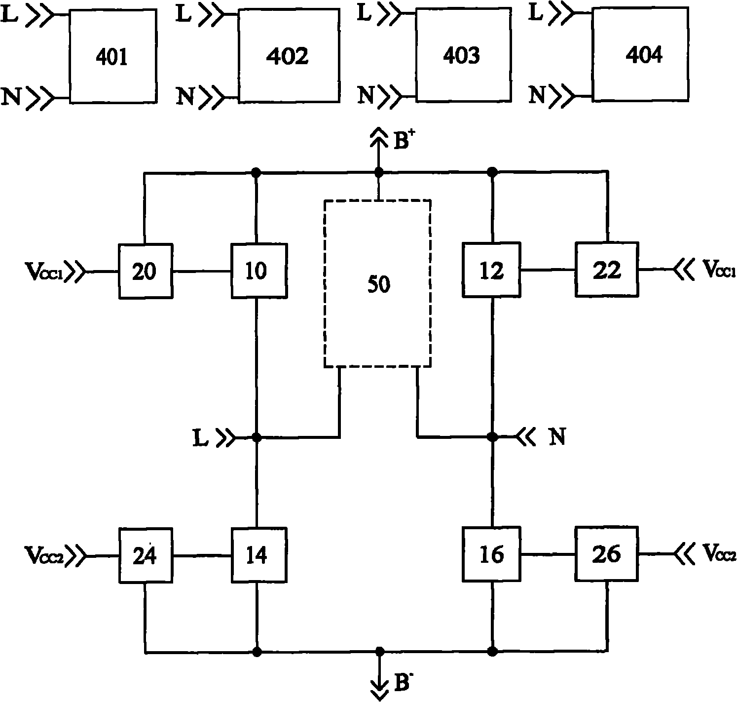
[0016] figure 1 A block diagram showing a gate-controlled bridge rectifier with an inrush current limiter according to the present invention, which includes a first AC input terminal L, a second AC input terminal N, and a first DC output terminal B + , a second DC output terminal B - , a first fixed voltage source terminal V cc1 , a second fixed voltage source terminal V cc2 , an inrush current limiter 50, a first positive polarity detector 401, a second positive polarity detector 402, a first negative polarity detector 403, a second negative polarity detector 404, a first positive polarity detector Driving circuit 20, a second positive polarity driving circuit 26, a first negative polarity driving circuit 24, a second negative polarity driving circuit 22, a first gate control transistor 10 without body diode, a second body diode with A gate control transistor 16, a first gate control transistor 14 with a body diode, a second gate control transistor 12 without a body diode....


PUM


Abstract

The invention relates to a grid-control bridge rectifier with a surge current limiter, comprising a first and a second alternating current input ends L and N, a first and a second direct current output ends B+ and B-, a first and a second fixed voltage source ends Vcc1 and Vcc2, a surge current limiter, two positive polarity detectors and two negative polarity detectors, two positive polarity drive circuits and two negative polarity drive circuits, two grid-control transistors of a body-containing diode and two grid-control transistors of a body-free diode. The two fixed voltage sources are respectively connected to Vcc1 and Vcc2 and referred to B+ and B-; the surge current limiter is provided with a first and a second input ends and an output end which are respectively connected to L, N and B+; the four polarity detectors are provided with the first and second input ends which are respectively connected to L and N; the four polarity drive circuits are provided with the first and second input ends and one output end which are respectively connected to Vcc1/Vcc2, B+/B- and the input end of the four grid control transistors which have one input end, and the first and second output ends which are respectively connected to the output ends of the four polarity drive circuits, L/N and B+/B-.

Description

technical field [0001] The invention relates to a grid-controlled bridge rectifier, in particular to a grid-controlled bridge rectifier with a surge current limiter, which can limit the surge current and improve rectification efficiency. Background technique [0002] Existing diode bridge rectifiers (diode bridge rectifiers) use four rectification diodes (rectification diodes) to rectify the AC input voltage into a DC output voltage; existing inrush current limiters (inrush current limiters) often use a thermistor ( thermistor) to limit inrush current. Despite the simple structure and cheap price, the forward voltage drop of the rectifier diode makes the diode bridge rectifier suffer from high conduction loss in high current applications; the negative temperature coefficient of the thermistor (negative temperature coefficient) makes the thermistor almost lose the function of inrush current limiter at high temperature. Contents of the invention [0003] To solve the above...

Claims


Application Information

Patent Timeline
Patent Type & Authority Applications(China)
IPC IPC(8): H02M7/219H02M1/32H02H9/02
Inventor 王志良余金生
Owner GLACIALTECH
Why Eureka
Try Eureka