Compensation method for rotor position angle of permanent-magnet motor

A technology of motor rotor and position angle, applied in the direction of electronic commutator, etc., can solve the problems of not being suitable for electric vehicles and hybrid vehicles, affecting the normal operation of electric vehicles and hybrid vehicles, etc.

Inactive Publication Date: 2010-12-22
CHERY AUTOMOBILE CO LTD
View PDF2 Cites 30 Cited by
  • Summary
  • Abstract
  • Description
  • Claims
  • Application Information

AI Technical Summary

Problems solved by technology

Such a treatment method will definitely affect the normal operation of electric veh...

Method used


Image

  • Compensation method for rotor position angle of permanent-magnet motor
  • Compensation method for rotor position angle of permanent-magnet motor

Examples


Embodiment 1

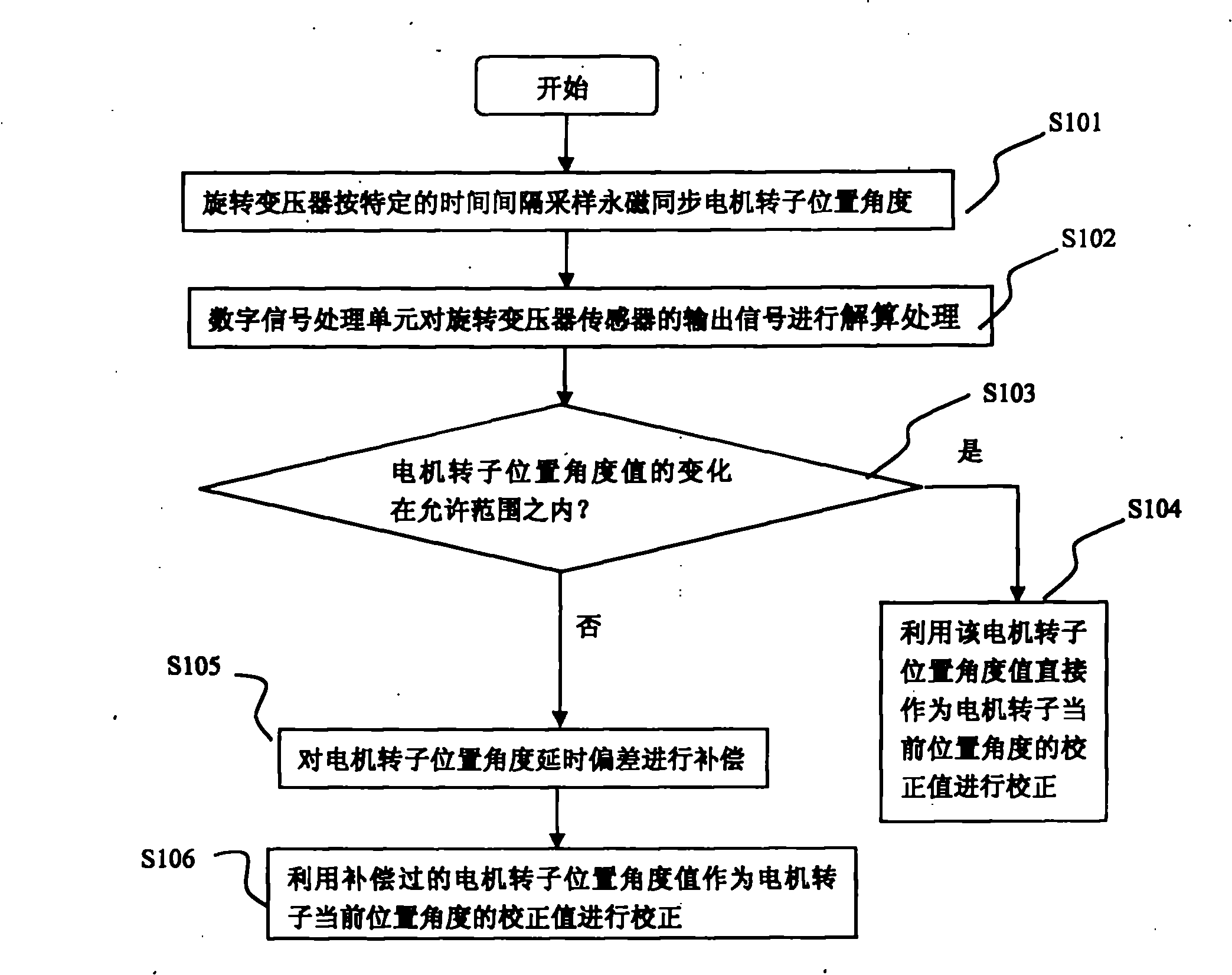
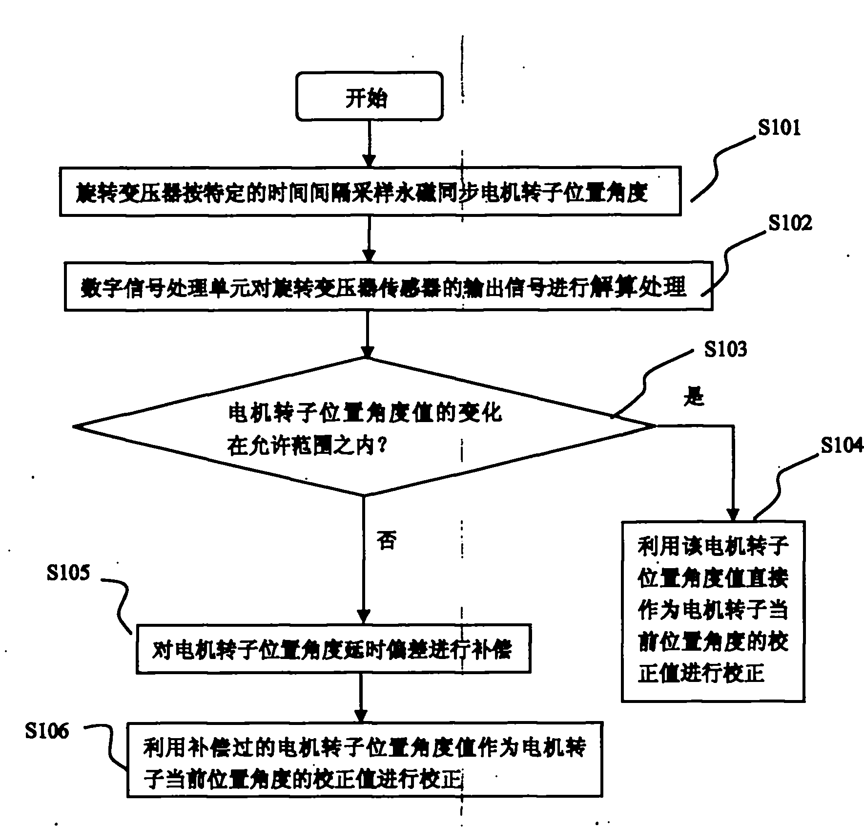
[0013] like figure 1 As shown, the compensation method for the rotor position angle of the permanent magnet motor in this embodiment includes the following steps:

[0014] S101: Utilize a resolver coaxial with the permanent magnet synchronous motor to sample the rotor position angle of the permanent magnet synchronous motor at specific time intervals;

[0015] S102: Perform calculation processing on the output signal of the resolver sensor by the digital signal processing unit;

[0016] S103: Judging the change of the motor rotor position angle, if the change of the motor rotor position angle value is within the allowable range, execute step S104, otherwise execute step S105;

[0017] S104: Use the motor rotor position angle value directly as a correction value for the current position angle of the motor rotor to correct;

[0018] S105: Compensating the motor rotor position angle delay deviation;

[0019] S106: Use the compensated motor rotor position angle value as a corre...


PUM


Abstract

The invention provides a compensation method for the rotor position angle of a permanent-magnet motor, which can enable a permanent-magnet synchronous motor to keep on stable operation under the conditions of a high speed and large rotary transformer errors. The method specifically comprises the following steps: sampling the rotor position angle of the permanent-magnet synchronous motor by using a rotary transformer coaxial with the permanent-magnet synchronous motor at a specific time interval, resolving output signals of a rotary transformer sensor by using a digital signal processing unit after each sampling operation, and judging whether the variation of the rotor position angle of the motor is within the allowed range; if so, directly using the rotor position angle value of the motor as a correction value of the current rotor position angle of the motor; and if not, calculating the correction value of the current rotor position angle of the motor based on the angular speed of the motor in the last sampling operation and the time interval between two consecutive sampling operations, and compensating for the time delay deviation of the rotor position angle of the motor by using a processor.

Description

technical field [0001] The invention belongs to the technical field of permanent magnet synchronous motors, in particular to the detection and compensation of the rotor position of permanent magnet synchronous motors applied to electric vehicle and hybrid vehicle systems. Background technique [0002] The permanent magnet synchronous motor has the advantages of small size, low loss, high efficiency, etc., and is very suitable for use in electric vehicle and hybrid vehicle systems. During use, the control of the permanent magnet synchronous motor is required to be very precise. In the permanent magnet synchronous control system, not only the motor is required to work in various complex environments, but also the motor's angle, speed, and torque control accuracy are very high, so it is required to detect and control the rotor position of the motor At present, the sensors used to detect the rotor position of permanent magnet synchronous motors include Hall sensors or photoelec...

Claims


Application Information

Patent Timeline
IPC IPC(8): H02P6/16
Inventor 陈立冲罗晓宋波王瑛
Owner CHERY AUTOMOBILE CO LTD
Why Eureka
Try Eureka