Cooling device of steel plate

A technology for cooling devices and steel plates, applied in quenching devices, heat treatment equipment, furnaces, etc., can solve problems such as inability to achieve uniform and symmetrical cooling on the center plane of plate thickness, unreasonable configuration of water flow impact areas, and limited cooling speed and thermal conductivity, etc., to achieve reasonable Control of mechanical properties, easy operation and maintenance, and improved coverage

Inactive Publication Date: 2010-12-29
CERI TECH
View PDF2 Cites 8 Cited by
  • Summary
  • Abstract
  • Description
  • Claims
  • Application Information

AI Technical Summary

Problems solved by technology

In the existing steel plate cooling equipment, the fundamental problem is that the configuration of the impact area of ​​the water flow is unreasonable; the gravity field has different effects on the upper and lower jets, resulting in a mismatch of the main heat transfer mechanism or a large cooling effect of the same h

Method used


Image

  • Cooling device of steel plate
  • Cooling device of steel plate
  • Cooling device of steel plate

Examples


Embodiment Construction

[0046] The technical solutions in the embodiments of the present invention will be clearly and completely described below with reference to the accompanying drawings in the embodiments of the present invention. Obviously, the described embodiments are only a part of the embodiments of the present invention, but not all of the embodiments. Based on the embodiments of the present invention, all other embodiments obtained by those of ordinary skill in the art without creative efforts shall fall within the protection scope of the present invention.

[0047]The specific embodiments of the steel plate cooling device of the present invention will be further described below with reference to the accompanying drawings.

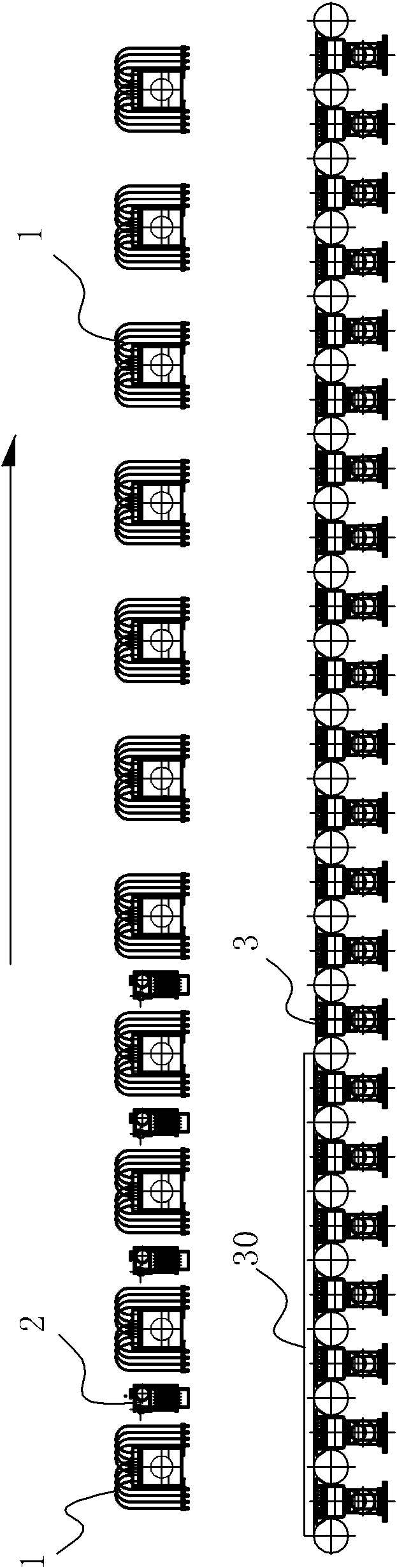
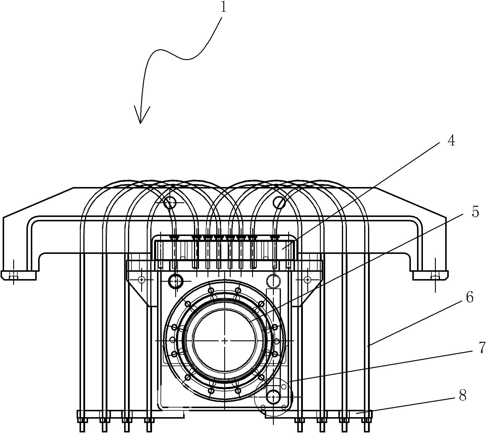
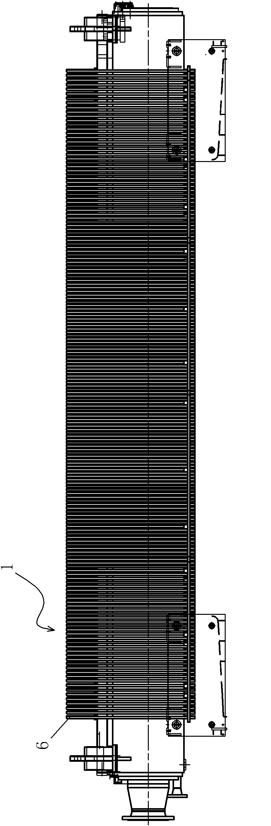
[0048] like figure 1 As shown, the steel plate cooling device of the present invention includes a U-shaped tube upper header 1 , an auxiliary upper header 2 and a lower header 3 . like figure 1 As shown, the steel plate cooling device of the present invention at leas...


PUM


Abstract

The invention provides a cooling device of a steel plate. The cooling device of the steel plate at least comprises a plurality of U-shaped upper collecting tubes located above the steel plate and arranged along the running direction of the steel plate, eight rows of U-shaped tubular nozzles are arranged along the running direction of each U-shaped upper collecting tube in order to improve the water spray capacity of unit time. By adopting the cooling device of the steel plate, low pressure water can be utilized to cool so as to reach a cooling speed required by quenching, therefore, the cooling device and a water supply system are simplified, and the energy consumption and the cooling cost are reduced.

Description

technical field [0001] The present invention relates to a steel plate cooling technology, in particular, to a steel plate cooling device. Background technique [0002] When the high temperature steel plate is cooled online after hot rolling, it is divided into two processes: accelerated cooling and direct quenching. Quenching is an important means to improve the strength of the steel plate. Direct quenching should be undertaken by two sets of devices and two sets of high and low pressure water supply systems, or by one set of devices and two sets of high and low pressure water supply systems. In order to obtain the cooling speed required for the quenching treatment, the high-temperature steel plate after hot rolling first enters the high-pressure cooling zone of the cooling device during the conveying process of the roller table, and uses high-pressure water of about 0.8MPa for rapid cooling, so that the temperature of the hardened layer of the steel plate decreases rapidly....

Claims


Application Information

Patent Timeline
IPC IPC(8): C21D1/667C21D9/46
Inventor 马连军钱振声宋敬稳陈爱华
Owner CERI TECH
Why Eureka
Try Eureka