Eureka AIR delivers breakthrough ideas for toughest innovation challenges, trusted by R&D personnel around the world.

Vacuum coating machine

A technology of vacuum coating machine and coating chamber, which is applied in vacuum evaporation coating, sputtering coating, ion implantation coating, etc., which can solve the problems of low production efficiency, large labor cost, and increased labor consumption.

Inactive Publication Date: 2010-12-29
HONG FU JIN PRECISION IND (SHENZHEN) CO LTD +1
View PDF0 Cites 21 Cited by
  • Summary
  • Abstract
  • Description
  • Claims
  • Application Information

AI Technical Summary

Problems solved by technology

When this kind of coating machine is in use, it is necessary to manually take out, insert, take up and take down the tray every time, so it greatly increases the consumption of manpower and affects the continuity of processing, resulting in low production efficiency and labor consumption. Big

Method used


Image

  • Vacuum coating machine
  • Vacuum coating machine
  • Vacuum coating machine

Examples


Embodiment Construction

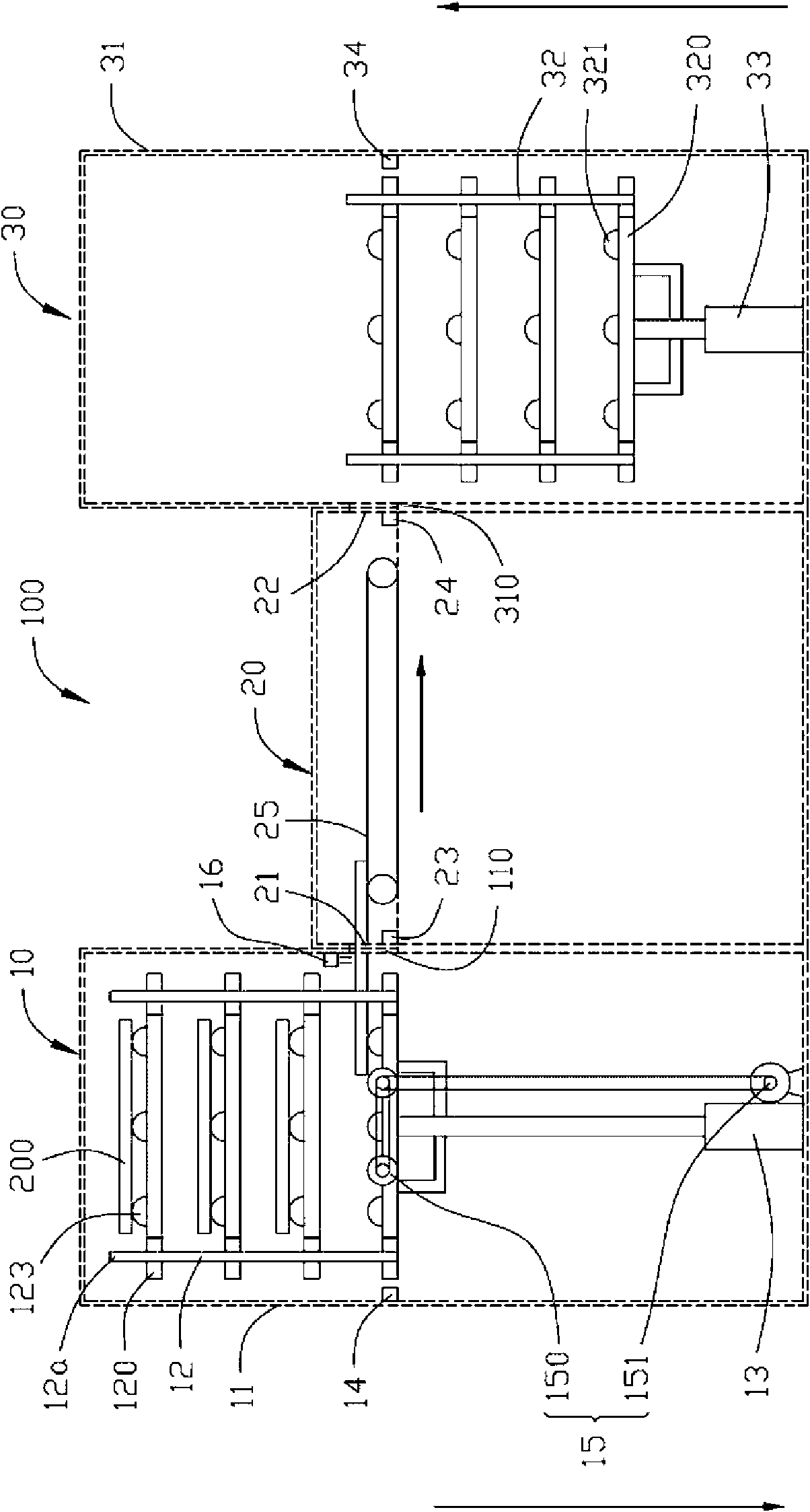
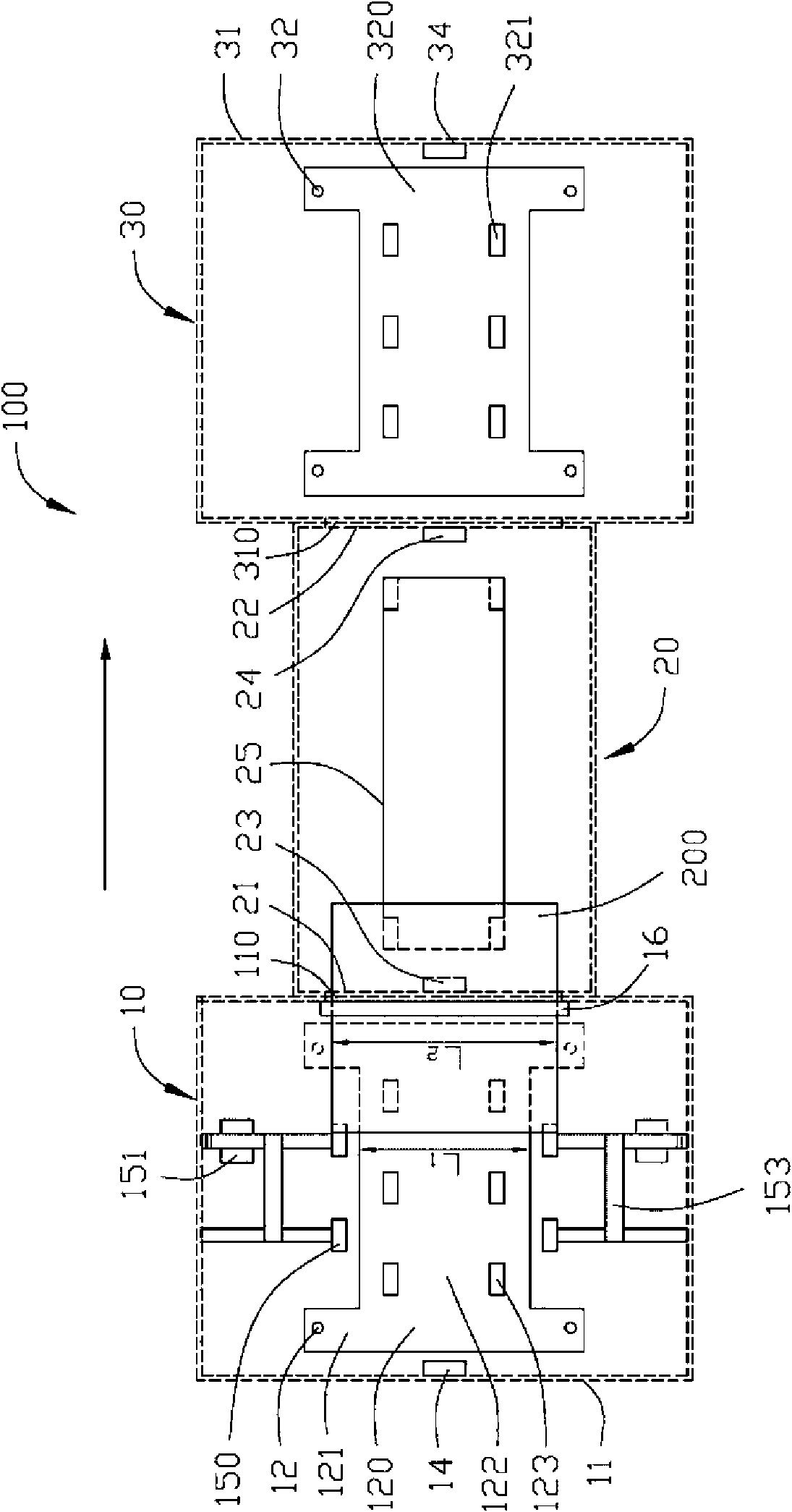
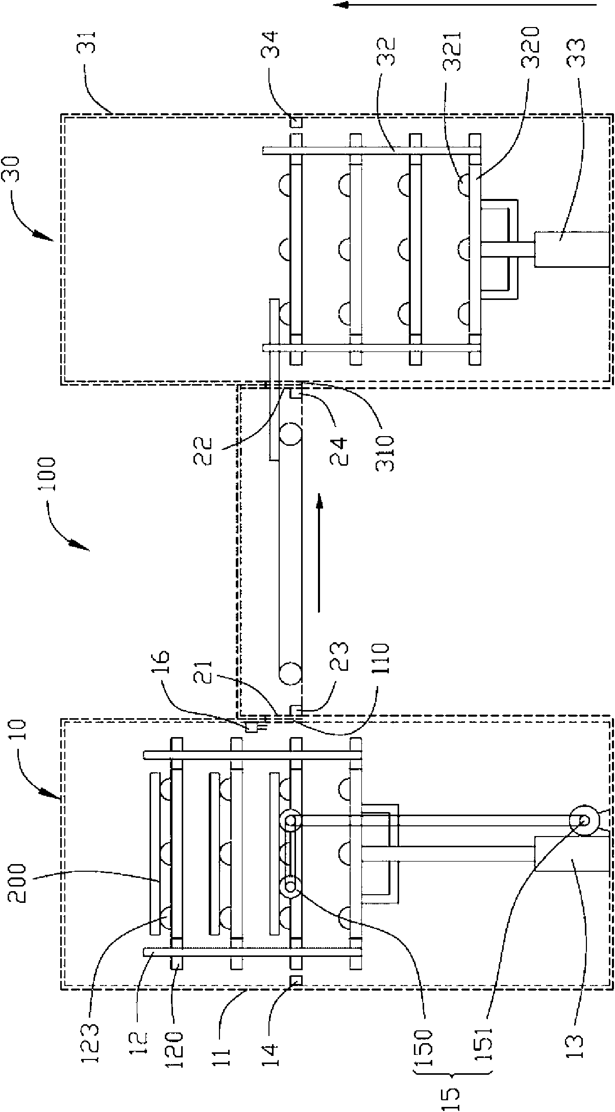
[0009] See figure 1 and figure 2 , a vacuum coating machine 100 provided in an embodiment of the present invention, the vacuum coating machine 100 is provided with a loading chamber 10 , a coating chamber 20 and an unloading chamber 30 sequentially from one end to the other end. The two ends of the coating chamber 20 are provided with a material inlet 21 and a material outlet 22 . The loading chamber 10 is connected to the material inlet 21 . The unloading chamber 30 is connected with the discharge port 22 . A first sensor 23 , a second sensor 24 and a conveyor belt 25 are installed in the coating chamber 20 , and the first sensor 23 is used to sense whether the carrier plate 200 carrying workpieces to be coated enters the coating chamber 20 completely. The first sensor 23 can be a position sensor or a displacement sensor. In this embodiment, the first sensor 23 is a position sensor. When the first sensor 23 senses that the carrier plate 200 has completely entered the co...


PUM


Abstract

The invention discloses a vacuum coating machine. The vacuum coating machine comprises a loading chamber, a coating chamber and an unloading chamber, wherein two ends of the coating chamber are provided with a feeding hole and a discharge hole. The loading chamber is connected with the feeding hole; and a loading frame, a first drive mechanism and a transmission device are arranged in the loading chamber. The loading frame bears a plurality of horizontal mutually-parallel loading trays; the first drive mechanism is fixed in the loading chamber, is connected with the loading frame, drives the loading frame to descend and can align each loading tray with the feeding hole; and the transmission device conveys the loading tray aligned with the feeding hole into the feeding hole. The unloading chamber is connected with the discharge hole, and an unloading frame and a second drive mechanism are arranged in the unloading chamber. The unloading frame is used for horizontally arranging the plurality of loading trays from the discharge hole layer by layer, the second drive mechanism is fixed in the unloading chamber, and the second drive mechanism is connected with the unloading frame and drives the unloading frame to ascend. The vacuum coating machine can perform batch loading and unloading, and can effectively reduce manpower and improve production efficiency.

Description

technical field [0001] The invention relates to a vacuum coating machine. Background technique [0002] When the existing vacuum coating machine is used, when loading and unloading the trays loaded with workpieces to be plated, each tray needs to be taken out manually, placed on one side, and then the next tray is loaded into the vacuum coating machine . When this kind of coating machine is in use, it is necessary to manually take out, insert, take up and take down the tray every time, so it greatly increases the consumption of manpower and affects the continuity of processing, resulting in low production efficiency and labor consumption. Big. Contents of the invention [0003] In view of this, it is necessary to provide a vacuum coating machine that can improve production efficiency. [0004] A vacuum coating machine includes a coating chamber, and two ends of the coating chamber are provided with a material inlet and a material outlet. The vacuum coating machine also...

Claims


Application Information

Patent Timeline
IPC IPC(8): C23C14/56C23C16/54
Inventor 蔡泰生
Owner HONG FU JIN PRECISION IND (SHENZHEN) CO LTD
Why Eureka
Eureka Blog
Learn More