
Fault diagnosis method for rotary machine

A technology for fault diagnosis and rotating machinery, applied in the testing of mechanical parts, the testing of machine/structural parts, measuring devices, etc. It can solve the problem of low resolution of the map, difficult to distinguish the vibration state of the long semi-axis, and difficult to give the strength structure. and other problems, to achieve high sensitivity, avoid misjudgment, and good stability.

Inactive Publication Date: 2012-08-29
陈先利 +1
View PDF0 Cites 0 Cited by
  • Summary
  • Abstract
  • Description
  • Claims
  • Application Information

AI Technical Summary

Problems solved by technology

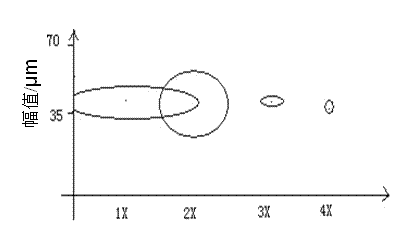
The holographic spectrum analysis technology uses an ellipse to represent the state of vibration at each multiplier frequency. However, when the amplitude of each harmonic has a large difference, it is difficult to express it completely with an ellipse, so the resolution of the spectrum is low.
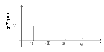
The full vector spectrum analysis technology uses the semi-major axis of the ellipse to represent the vibration intensity at each octave. The resolution of the spectrum is high, but it is difficult to distinguish the vibration state when the semi-major axis is equal and the eccentricity is different.
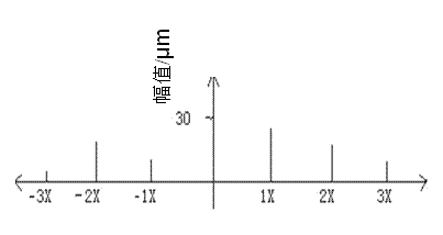
The full-spectrum analysis technology is to display the radii of the two positive circles decomposed by the axis trajectory ellipse on the positive and negative frequency axes at each multiplier frequency, and compare the amplitudes on the positive and negative frequency axes of the two under the same harmonic. Judging the direction of precession, the resolution of the map is high, but since judging the magnitude of the rotor vibration intensity at each frequency needs to be determined by adding the amplitudes on the positive and negative frequency axes of the same harmonic, the expression of the intensity is carried out indirectly, which is very difficult. Difficult to give a representation of the overall strength structure

Method used


Image

  • Fault diagnosis method for rotary machine
  • Fault diagnosis method for rotary machine
  • Fault diagnosis method for rotary machine

Examples


Embodiment Construction

[0034] The response of rotating machinery to changes in certain process parameters and operating parameters is a complete set of process signals, which are of great value for analyzing the stability of equipment, performing fault diagnosis and parameter identification. Through the analysis of a group of process signals, it is possible to analyze the vibration characteristics of the rotor, query the reasons for the amplitude and phase changes, obtain key parameters such as the critical speed of the actual operation of the unit, determine the unbalanced response of the rotor, and study the resonance of structures and components, etc. It is one of the important basis for fault diagnosis.

[0035] In the present invention, on the basis of the existing holographic spectrum, full vector spectrum, and full spectrum analysis technology, the relationship between each parameter, the rotor system parameter, and the excitation force parameter is systematically analyzed, and the existing ro...


PUM


Abstract

The invention relates to a fault diagnosis method for a rotary machine, comprising the following steps: acquiring original vibration signals of two perpendicular channels on a vibration measurement section, and carrying out anti-aliasing filtering, low pass filtering and the like on collected signals; removing unnecessary interference noise signals, adopting complex FFT conversion to calculate a primary vibration vector a and a secondary vibration vector b; further calculating relevant numerical values of a vector area and a vector vibration ratio and obtaining graphs of the vector area and the vector vibration ratio relative to various variables; and utilizing the vector area to express the vibration strength and direction of a measuring point under single frequency, and utilizing the vector vibration ratio to express eccentricity size, flat degree and forward and reverse precessional motion of a vector ellipse. The method has the advantage of good effect in diagnosing the steady-state faults and instantaneous faults of the rotary machine; and the vector area graph and the vector vibration ratio are combined to diagnose the faults, thus the erroneous judgment generated by only utilizing the vector area is avoided, the diagnosis accuracy is enhanced, and the diagnosis efficiency and precision are improved.

Description

technical field [0001] The patent of the present invention belongs to the field of mechanical fault diagnosis, and specifically relates to the field of fault diagnosis and control of rotating machinery. Background technique [0002] The detection of rotating machinery is generally completed by two probes with the same section perpendicular to each other. However, due to the eddy characteristics of the rotor, the information detected by any probe cannot reflect the actual status of the unit in terms of spectrum value and structure. In many The difference in the situation is very large, which will directly affect the diagnosis result and cause misjudgment. In order to objectively reflect the vibration state of the rotor and avoid misjudgments caused by it, many scholars and researchers have done a lot of research and application work, including domestic holographic spectrum analysis technology, full vector spectrum analysis technology and foreign full spectrum analysis technol...

Claims


Application Information

Patent Timeline
Patent Type & Authority Patents(China)
IPC IPC(8): G01M13/00G01M7/02
Inventor 陈先利韩捷
Owner 陈先利
Learn More