Approximate target object detecting method and device

A target and feature point detection technology, applied in the field of image processing, can solve problems such as inaccurate detection results

Active Publication Date: 2010-12-29
NEUSOFT REACH AUTOMOTIVE TECH SHANGHAI CO LTD
View PDF5 Cites 29 Cited by
  • Summary
  • Abstract
  • Description
  • Claims
  • Application Information

AI Technical Summary

Problems solved by technology

[0004] The purpose of the embodiment of the present application is to provide a method and device for detecting an approaching object, s...

Method used


Image

  • Approximate target object detecting method and device
  • Approximate target object detecting method and device
  • Approximate target object detecting method and device

Examples


no. 1 example

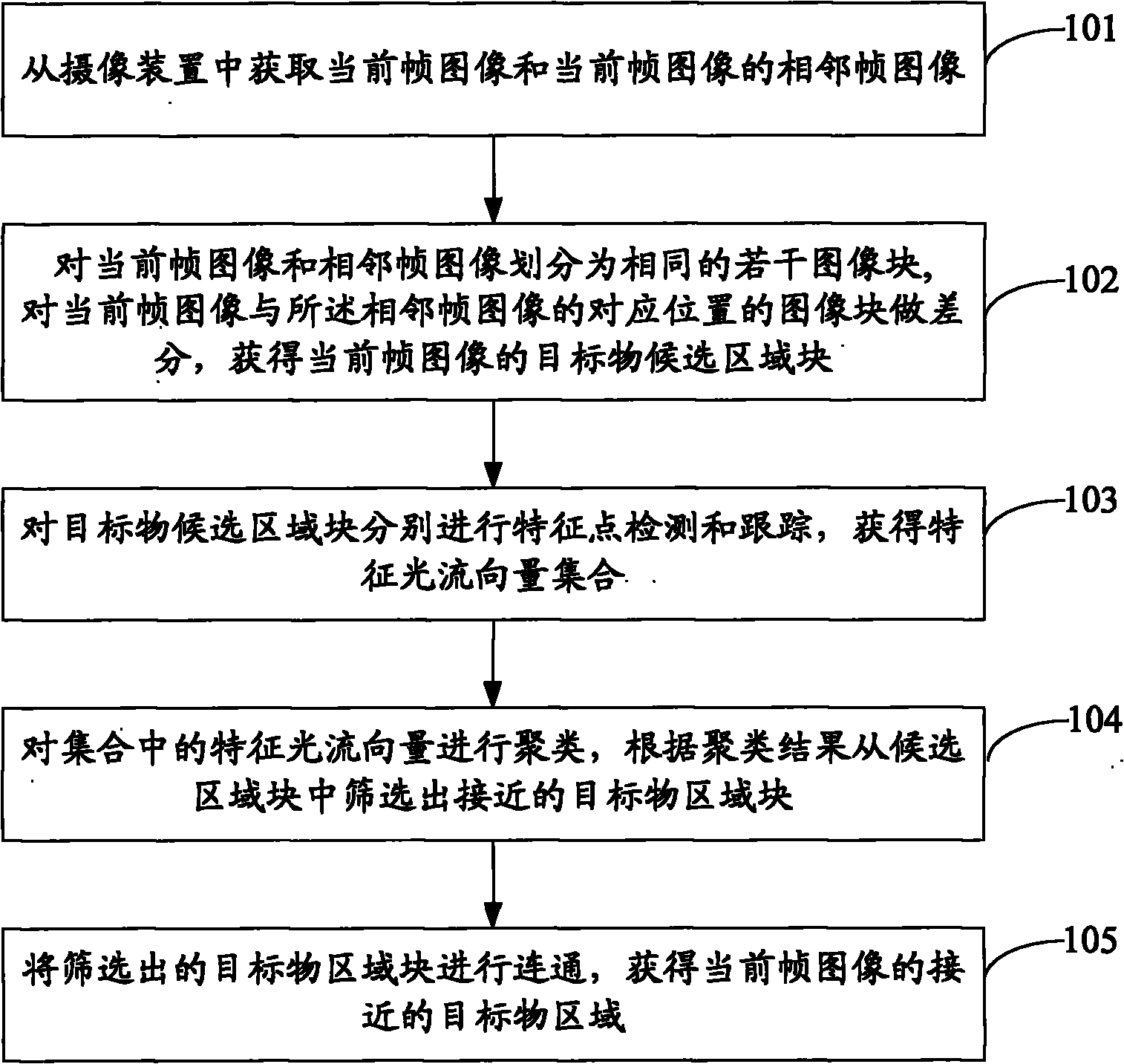
[0065] see figure 1 , which is the flow chart of the first embodiment of the approaching object detection method of the present application:

[0066] Step 101: Obtain the current frame image and adjacent frame images of the current frame image from the camera.

[0067] Step 102: Divide the current frame image and the adjacent frame image into the same number of image blocks, make a difference between the current frame image and the image blocks at the corresponding positions of the adjacent frame image, and obtain the target object candidate area block of the current frame image .

[0068] Specifically, the current frame image and the adjacent frame image are divided into several identical image blocks, and the difference operation is respectively performed on the image blocks corresponding to each other in the current frame image and the adjacent frame image, when the difference When the result of the calculation is greater than the preset threshold, the corresponding image...

no. 1 example

[0132] see Figure 5 , which is the block diagram of the first embodiment of the object detection device close to the present application:

[0133] The apparatus for detecting an approaching object includes: an acquisition unit 510 , a difference unit 520 , a detection unit 530 , a clustering unit 540 and a connection unit 550 .

[0134] Wherein, the obtaining unit 510 is configured to obtain the current frame image and the adjacent frame images of the current frame image from the camera device;

[0135] The difference unit 520 is used to divide the current frame image and the adjacent frame image into the same number of image blocks, and make a difference between the image blocks corresponding to the current frame image and the adjacent frame image to obtain the current frame The target object candidate area block of the image;

[0136] A detection unit 530, configured to perform feature point detection and tracking on the target candidate area blocks, to obtain a set of fe...

no. 2 example

[0139] see Figure 6 , which is a block diagram of the second embodiment of the object detection device close to the present application:

[0140] The apparatus for detecting an approaching object includes: an acquisition unit 610 , a difference unit 620 , a detection unit 630 , a tracking unit 640 , a deletion unit 650 , a clustering unit 660 and a connection unit 670 .

[0141] Wherein, the acquisition unit 610 is configured to acquire the current frame image and the adjacent frame images of the current frame image from the camera device;

[0142] The difference unit 620 is used to divide the current frame image and the adjacent frame image into the same number of image blocks, and make a difference between the image blocks corresponding to the current frame image and the adjacent frame image to obtain the current frame The target object candidate area block of the image;

[0143] A detection unit 630, configured to perform feature point detection and tracking on the targe...


PUM


Abstract

The invention discloses an approximate target object detecting method and an approximate target object detecting device. The method comprises the following steps of: acquiring a current frame image and a frame image adjacent to the current frame image from a camera device; dividing the current frame image and the adjacent frame image into same number of image blocks, and differencing image blocks at corresponding positions of the current frame image and the adjacent frame image to obtain target object candidate area blocks of the current frame image; respectively performing characteristic point detection and tracking on the target object candidate area blocks to obtain a characteristic light stream vector set; clustering characteristic light stream vectors in the set, and screening approximate target object area blocks from the candidate area blocks according to a cluster result; and connecting the screened approximate target object area blocks to obtain an approximate target object area of the current frame image. An image frame block analysis method is adopted for detecting motion targets, types of the approximate target objects are not limited, and the method is also suitable for detecting rigid target objects and non-rigid target objects, and has the advantages of simple calculation, accurate detection and high speed of detection.

Description

technical field [0001] The present application relates to the technical field of image processing, in particular to a method and device for detecting an approaching object. Background technique [0002] During the driving process of the vehicle, due to the existence of the blind spot of the vehicle or the negligence of the driver, the target objects (such as other vehicles, motorcycles, etc.) approaching the vehicle are likely to become a safety hazard for the vehicle. If the driver does not find the target object, then It is easy to be dangerous during driving. In order to overcome the potential safety hazards of the vehicle, it is necessary to detect the target objects in the surrounding area of ​​the vehicle, and remind the driver according to the detection results. [0003] In the prior art, the optical flow method can be used to detect the target object approaching the vehicle, that is, to detect the feature points of the whole image, and calculate the optical flow rel...

Claims


Application Information

Patent Timeline
IPC IPC(8): G06T7/00G06T7/20G08G1/017
Inventor 刘威于红菲袁淮
Owner NEUSOFT REACH AUTOMOTIVE TECH SHANGHAI CO LTD
Why Eureka
Try Eureka