Energy machine of electric energy circulating machine

A technology of motors and capabilities, applied in the direction of electrical components, electromechanical devices, etc., can solve problems such as centrifugal disintegration, small frictional resistance, and high material requirements

Inactive Publication Date: 2010-12-29
王鑫弘
View PDF0 Cites 16 Cited by
  • Summary
  • Abstract
  • Description
  • Claims
  • Application Information

AI Technical Summary

Problems solved by technology

The flywheel system company in the United States has detailed data. The speed of the flywheel is generally 50,000 to 200,000 revolutions per minute, but it must run in a vacuum. Its bearings are magnetically suspended, and the frictional resistance is very small, ensuring its long-term operation. , the running time is 5 hours to 7 hours, but the manufacturing cost is high, the charging time is long, the running time is short, and the number of rotations of the flywheel is too high, which requires high material requirements. The general material will be centrifugally disintegrated and exploded.

Method used


Image

  • Energy machine of electric energy circulating machine
  • Energy machine of electric energy circulating machine
  • Energy machine of electric energy circulating machine

Examples


Embodiment Construction

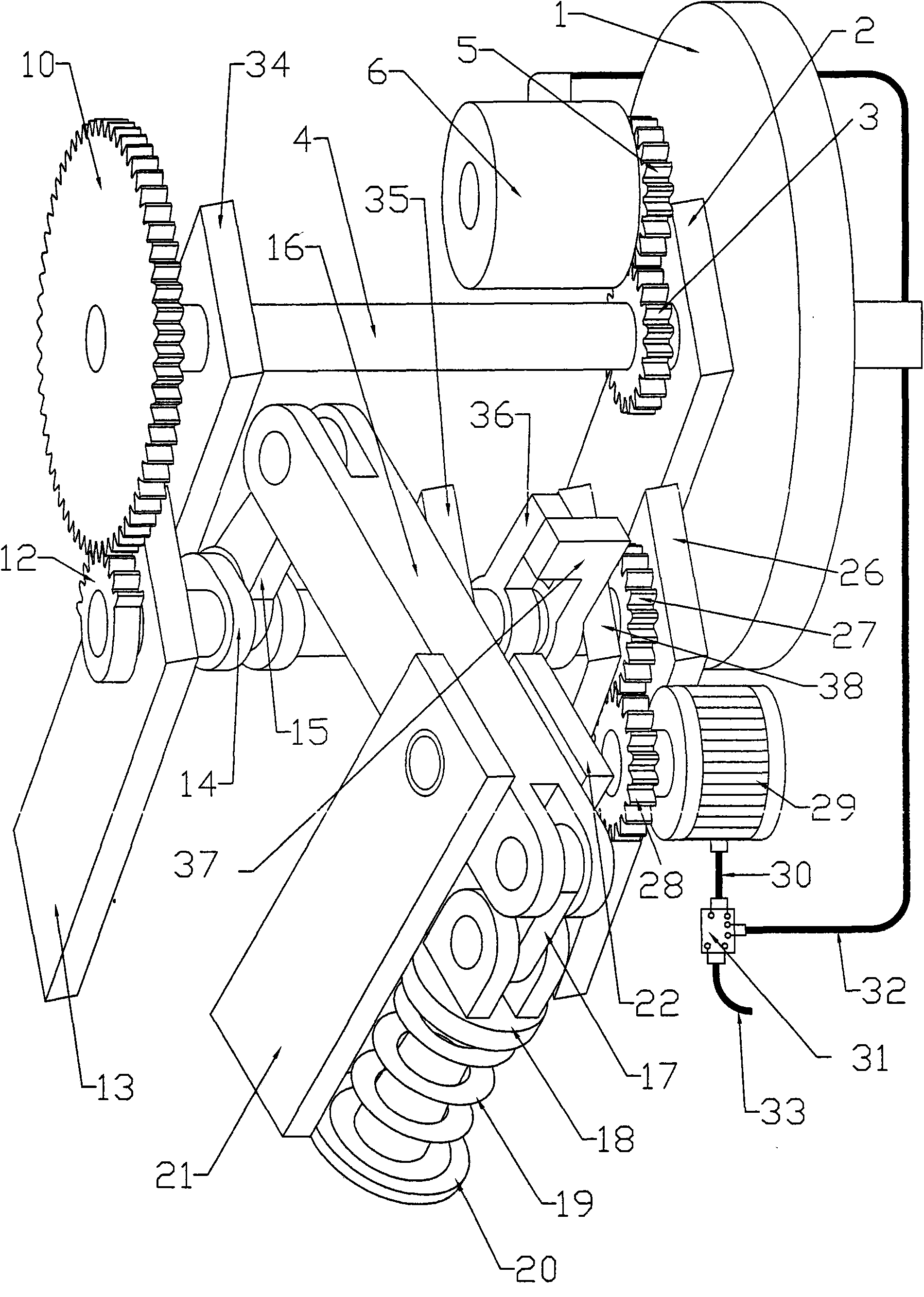
[0034] The present invention will be described in further detail below in conjunction with accompanying drawing and specific embodiment: the present invention has nine basic principle technical schemes.

[0035] figure 1 In the shown first embodiment, each scheme of flywheel 1 is uniformly arranged on the right end of power take-off shaft 4, and the front of the left end face of flywheel 1 is power take-off bearing support I 2, and the left side of power take-off bearing support I 2 is It is the power output gear 3, the power output gear 3 is meshed with the generator gear 5, the generator gear 5 is connected to the rotating shaft of the generator 6, the generator 6 is arranged in parallel with the power output shaft 4, and the left end of the power output gear 3 The front front is the work output driven pinion 7, and the left end face front of the work output driven pinion 7 is double bearing support I 8, and the left end of the power output shaft 4 is supported by the double...


PUM


Abstract

The invention relates to an energy machine of an electric energy circulating machine, which mainly comprises a flywheel, a generator, a gear, a motor, a pushing gear, a pushed gear, a semicircular gear, a crankshaft, a main connecting rod, a lever, a spring, a single-fluke coupling clutch, a castellated clutch, an inner pawl pushed gear, a ratchet, a pawl, a rack, an air-pressure spring, a cylindrical cam, a belt pulley, a belt, a chain wheel, a chain, a conical gear, a cam, a gravitational potential energy body and an elastic potential energy body which can be mutually assembled to form an acceleration and deceleration mechanism. The energy machine can store the energy for above 10 hours. The energy machine has the advantages of smart and simple structure, convenient and easy manufacturing, long running time, and low cost. The energy machine can be applied to power generation and all the places needing power such as automobile power, ship power, plane power, industrial power and the like. Furthermore, the energy machine can work under the high-temperature and low-temperature environment.

Description

technical field [0001] The invention relates to an electric energy circulation mechanical capacity motive. Background technique [0002] Existing flywheel accumulators or elastic potential energy accumulators. The energy storage time is short. They are all transient energy storage. Many patents related to flywheels and elastic potential energy have been applied to the State Intellectual Property Office of China. The following items, 200720035408. 8, 200410044410. 2, 03826182. 0, 200410077390. 9, 02132762. 9, 200710053636, the manufacturing technology that has been used and disclosed in the United States must operate in a vacuum, and the flywheel bearing adopts a magnetic levitation structure. The flywheel system company in the United States has detailed data. The speed of the flywheel is generally 50,000 to 200,000 revolutions per minute, but it must run in a vacuum. Its bearings are magnetically suspended, and the frictional resistance is very small, ensuring its long-te...

Claims


Application Information

Patent Timeline
Patent Type & Authority Applications(China)
IPC IPC(8): H02K53/00
Inventor 王鑫弘
Owner 王鑫弘
Why Eureka
Try Eureka