LED control circuit
A control circuit and control terminal technology, applied in the control field, can solve the problems of wasting power, failure to work normally, projector power and brightness deviation, etc., and achieve the effect of improving utilization efficiency
- Summary
- Abstract
- Description
- Claims
- Application Information
AI Technical Summary
Problems solved by technology
Method used
Image

Examples
Embodiment Construction
[0010] The embodiments of the present invention will be further described in detail below in conjunction with the accompanying drawings.
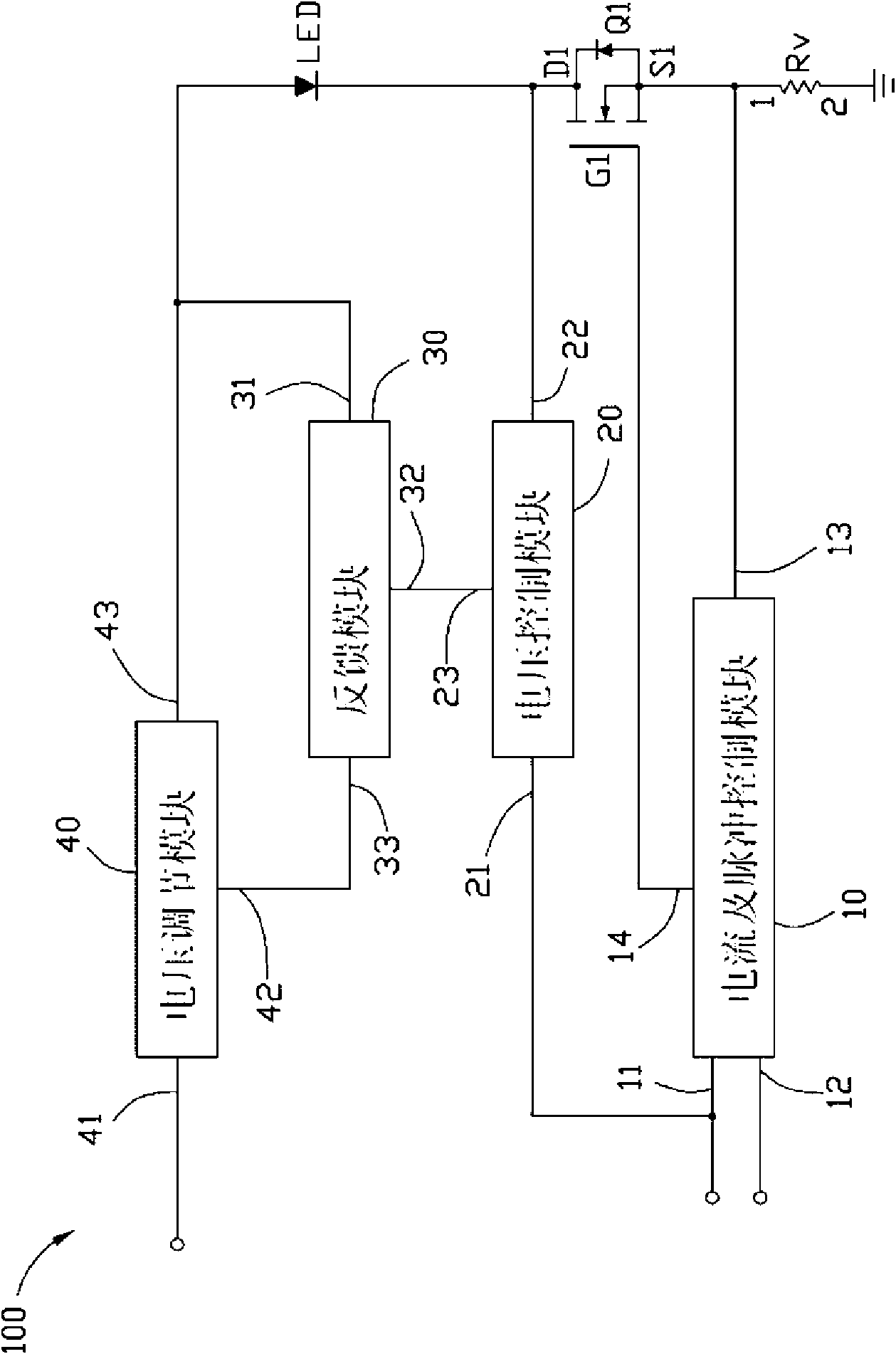
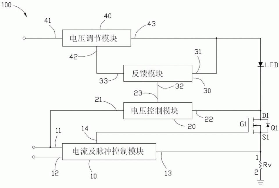
[0011] see figure 1 and figure 2 , which is the LED control circuit 100 according to the embodiment of the present invention, which is used to control the light emission of one LED. The LED has a forward voltage and a forward current, the forward voltage is the voltage drop required to be consumed between the anode and the cathode of the LED when the LED is working, and the forward current is the voltage that flows through the LED when the LED is working. Anode and cathode currents.
[0012] The LED control circuit 100 includes a current and pulse control module 10 , a first voltage control resistor Q1 , a voltage control module 20 , a feedback module 30 , a voltage regulation module 40 and a voltage dividing resistor RV.
[0013] The current and pulse control module 10 includes a first input terminal 11 , a second input terminal 12 , a...
PUM
 Abstract
Description
Claims
Application Information
 - R&D
- Intellectual Property
- Life Sciences
- Materials
- Tech Scout
- Unparalleled Data Quality
- Higher Quality Content
- 60% Fewer Hallucinations
Browse by: Latest US Patents, China's latest patents, Technical Efficacy Thesaurus, Application Domain, Technology Topic, Popular Technical Reports.
© 2025 PatSnap. All rights reserved.Legal|Privacy policy|Modern Slavery Act Transparency Statement|Sitemap|About US| Contact US: help@patsnap.com