Balling mechanism of steel ball rolling machine

A ball forming and ball machine technology, applied in the direction of mechanical equipment, bearing components, shafts and bearings, etc., can solve the problems of difficult control of parallel distance error, difficulty in meeting the requirements of ball forming roller adjustment and long-term maintenance, and difficulty in adjustment, etc., to achieve Guarantee the effect of roundness

Active Publication Date: 2011-01-05
CHANGSHU FEIFAN METALWORK
View PDF5 Cites 19 Cited by
  • Summary
  • Abstract
  • Description
  • Claims
  • Application Information

AI Technical Summary

Problems solved by technology

But there is following shortcoming in this patent scheme: the one, because there must be fit gap between slide block and axle seat and adjusting screw rod and slide block, thereby with regard to a pair of axle seat of a ball forming roller, this pair of axle seat is difficult Ideally located on a straight line, that is to say, the error between a pair of shaft seats is difficult to control the degree of due take, and then in terms of two pairs of roller seats of a pair of ball forming rollers (each ball forming roller There is a pair of shaft seats), the parallel distance error between adjacent shaft seats is also difficult to control, and the parallel distance error of the shaft seat directly affects the parallel distance of the ball forming roller; The reaction force of the reaction force, the displacement of a pair of shaft seats of the same ball forming roller is not the same, that is to say, it is impossible for a pair of shaft seats of the same ball forming roller to have a step-by-step displacement objectively, which will bring a certain degree of adjustment to the shutdown. The third is that the above-mentioned patented scheme is suitable for rolling copper balls with relatively soft material, good ductility and relatively small size (diameter), so if the patented structure is applied to rolling steel balls, especially When rolling large-sized steel balls, the above-mentioned adjustment device for the shaft seat, which only consists of a slider and an adjustment screw, is difficult to meet the requirements for the adjustment and long-term maintenance of the parallelism of the ball forming rollers.

Method used


Image

  • Balling mechanism of steel ball rolling machine
  • Balling mechanism of steel ball rolling machine

Examples


Embodiment Construction

[0015] In order to enable the examiners of the patent office, especially the public, to understand the technical essence and beneficial effects of the present invention more clearly, the applicant will describe in detail below in conjunction with the accompanying drawings in the form of embodiments, but none of the descriptions of the embodiments is a description of the present invention. Restriction of the inventive solution, any equivalent transformation made according to the concept of the present invention which is only in form but not in substance shall be regarded as the scope of the technical solution of the present invention.

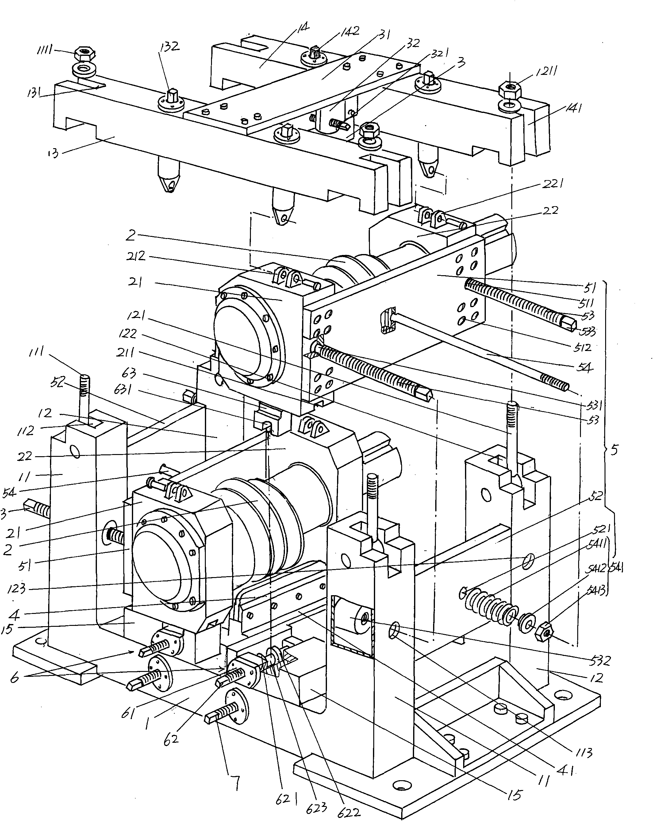
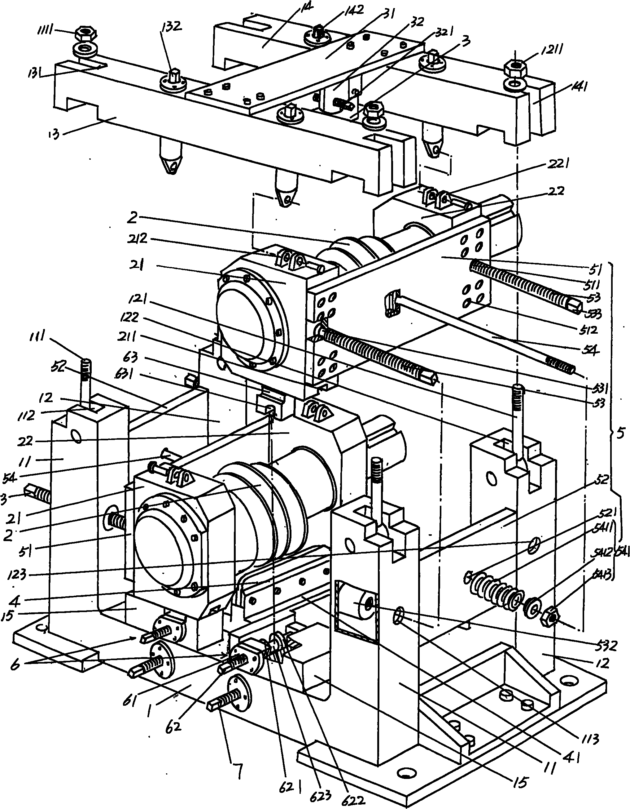
[0016] please see figure 1 , provides the ball forming mechanism of the preferred ball rolling machine considered by the applicant, the support 1 (also called frame) of the ball forming mechanism has a pair of first support columns 11, a pair of second support columns 12, a The first upper beam 13 and a second upper beam 14, a pair of first and ...


PUM


Abstract

The invention relates to a balling mechanism of a steel ball rolling machine, belonging to steel ball processing machinery. The balling mechanism comprises a pair of first support columns, a pair of second support columns, a support of a first upper beam, a support of a second upper beam, a pair of balling rollers, an upper ball barrier plate, a lower ball barrier plate and a pair of balling roller parallel distance adjusting devices. The balling roller parallel distance adjusting devices comprise a connecting plate, an elastic device seat plate, a pair of adjusting screw rods and a pull rod, wherein one end of the connecting plate is fixed with a first shaft seat, and the other end is fixed with a second shaft seat; one end of the elastic device seat plate is fixed with the first support columns, and the other end is fixed with the second support columns; one end of one adjusting screw rod is connected with one end of the connecting plate, the other end is connected with the first support columns, one end of the other adjusting screw rod is connected with the other end of the connecting plate, and the other end is connected with the second support columns; and one end of the pull rod is fixed with the middle part of the connecting plate, the other end penetrates through the elastic device seat plate, and the rod body of the pull rod stretching out of the elastic device seat plate is provided with an elastic device. The roundness of rolled steel balls is ensured, and the technological requirement for rolling large-diameter steel balls is satisfied.

Description

technical field [0001] The invention belongs to the technical field of steel ball processing machinery, and in particular relates to a ball forming mechanism of a steel ball rolling machine, which is used for rolling rolled steel balls into spheres. Background technique [0002] Chinese invention patent ZL200710023538.4 discloses the ball forming mechanism of the bar rolling machine, and the patented scheme can basically guarantee the roundness of the rolled ball. As known in the industry, the roundness of the ball is guaranteed by the parallelism of a pair of ball forming rollers. When a pair of ball forming rollers are in working condition, on the one hand, the bar is rolled into a ball, but at the same time the ball is rolled into a ball. It also produces a strong reaction force on the ball forming rollers, subtly changing the parallelism of a pair of ball forming rollers, especially the larger the diameter of the ball and the higher the hardness of the bar, the more diff...

Claims


Application Information

Patent Timeline
Patent Type & Authority Applications(China)
IPC IPC(8): B21H1/14
Inventor 陈刚
Owner CHANGSHU FEIFAN METALWORK
Why Eureka
Try Eureka