Free-wheel cage ring with centrifugal-force lifting

A technology of one-way clutches and cages, which is applied in the direction of one-way clutches, clutches, mechanical equipment, etc., can solve the problems of functional effects, operator hazards, one-way clutch failures, unevenness, etc., to simplify the manufacturing process, Accurate and firm guide surface configuration, the effect of improving positioning accuracy

Active Publication Date: 2014-05-28
RINGSPANN
View PDF5 Cites 0 Cited by
  • Summary
  • Abstract
  • Description
  • Claims
  • Application Information

AI Technical Summary

Problems solved by technology

This is of great importance, since even a small amount of material wear on the active body can cause uneven action which impairs functionality and eventually lead to freewheel failures which can be dangerous for the operator

Method used


Image

  • Free-wheel cage ring with centrifugal-force lifting
  • Free-wheel cage ring with centrifugal-force lifting
  • Free-wheel cage ring with centrifugal-force lifting

Examples


Embodiment Construction

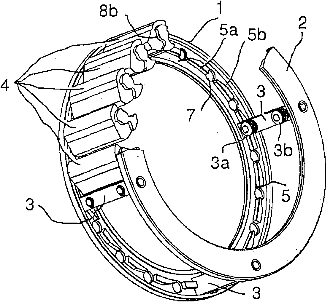
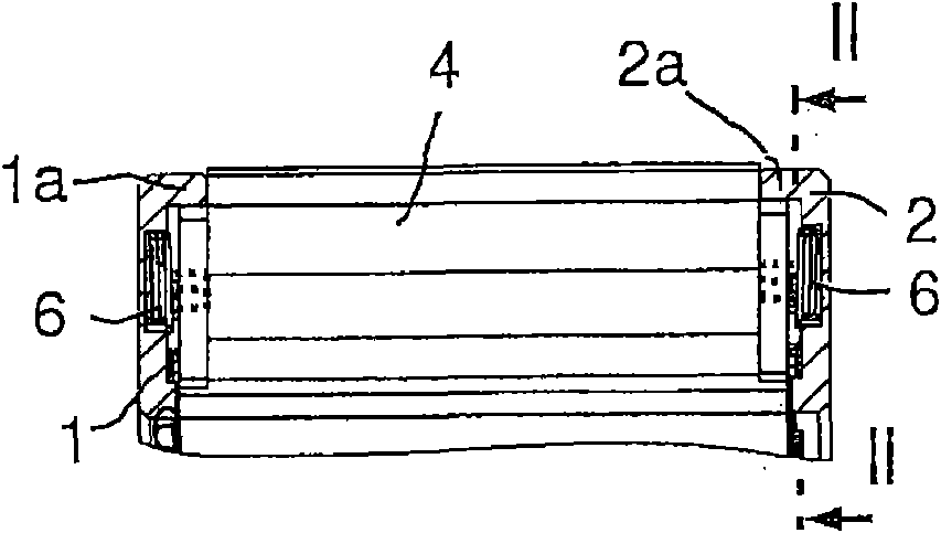
[0043] Figure 1 to Figure 5 A first embodiment of the one-way clutch cage according to the present invention is shown. The two annular end pieces 1 and 2 are connected to each other in parallel and concentrically by a plurality of axially extending connecting pins 3 . Each connecting pin 3 comprises two spring-loaded friction heads 3a, 3b for synchronizing the cage with the inner ring of the one-way clutch (not shown).

[0044] A plurality of action bodies 4 are arranged between (two) end pieces, figure 1 For the sake of clarity, only the active body in the upper left quarter of the one-way clutch cage is shown.

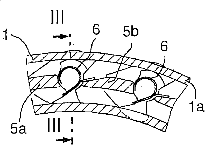
[0045] On the end sides facing each other, the end pieces each have a concentric flange 5 which is interrupted by a notch for forming the guide surface. For example, in figure 1 , 2 The two remaining webs 5 a and 5 b of the flange 5 are shown in and 4 . Guide surfaces are formed between the tabs by notches ( Figure 4 In 5c and 5d), the guide surface guides...


PUM


Abstract

A free-wheel cage ring, having two annular flanged disks that extend radially and are connected to each other to form an axial intermediate space and have clamping bodies therebetween pivotally arranged in the cage ring and are biased for coupling by a spring, the clamping bodies perform, due to centrifugal force, a pivoting motion for decoupling against the spring force, and at least two guide surfaces are allocated to each clamping body in its axial extent, that engage opposite end peripheral regions of the clamping body, guide them at least in the peripheral direction, and have a break through which the clamping bodies extend to a radially inner clamping surface. The axial length of the clamping body radially inner clamping surface is equal to the total length of the clamping body. The guide surfaces are each formed integrally by recesses on opposite end faces of the flanged disks.

Description

technical field [0001] The invention relates to a one-way clutch (ring) cage according to the preamble of claim 1 The one-way clutch retainer comprises two substantially radially extending annular end pieces / edge pieces, said end pieces being connected to each other forming an axial gap, with a plurality of functions between said end pieces body / wedge, the action body is arranged in a swingable manner in the cage and is prestressed in the engagement direction by at least one helical torsion spring; Oscillating motion acting in the direction of separation. At least two guide surfaces are assigned to each active body in its axial extent, which engage on the opposite end peripheral regions of the active body, at least in the circumferential direction of the end piece Guide the actor above. Background technique [0002] In the case of freewheels with centrifugal disengagement, it is known that during freewheeling the cage moves together with the freewheel outer ring, while t...

Claims


Application Information

Patent Timeline
Patent Type & Authority Patents(China)
IPC IPC(8): F16D41/07
CPCF16D41/073F16D41/07
Inventor S·雅克韦特K·蒂姆特纳R·莫勒
Owner RINGSPANN
Why Eureka
Try Eureka