Shaft seal structure

A shaft seal and sealing lip technology, applied in the field of mechanical engineering, can solve problems such as voiding, close sealing lips, and misalignment, and achieve the effects of improving distribution uniformity, reducing deformation amplitude, and increasing followability.

Active Publication Date: 2011-01-05
ZHEJIANG HONGYOU AIR COMPRESSOR MFG
View PDF7 Cites 6 Cited by
  • Summary
  • Abstract
  • Description
  • Claims
  • Application Information

AI Technical Summary

Problems solved by technology

[0003] The shaft seal of the above-mentioned traditional moving parts has a disadvantage, that is, the main body of the shaft seal is fastened by the end cover or cover plate. When the moving rod vibrates or swings, the axis of the inner hole of the shaft sealing main body and the axis of the moving rod will be separated. There is a phenomenon of misalignment. At this time, the shaft seal is biased by the moving rod, which makes the bonding force of the shaft seal to the shaft of the moving rod unbalanced. In other words, the sealing lip appears elliptical deformation under the action of the moving rod. The sealing lip at a certain place cannot be close to the shaft of the moving rod or even out of space (especially at one end of the long axis of the deformed ellipse and its vicinity), which will easily lead to the failure of the shaft seal

Method used


Image

  • Shaft seal structure
  • Shaft seal structure
  • Shaft seal structure

Examples


Embodiment Construction

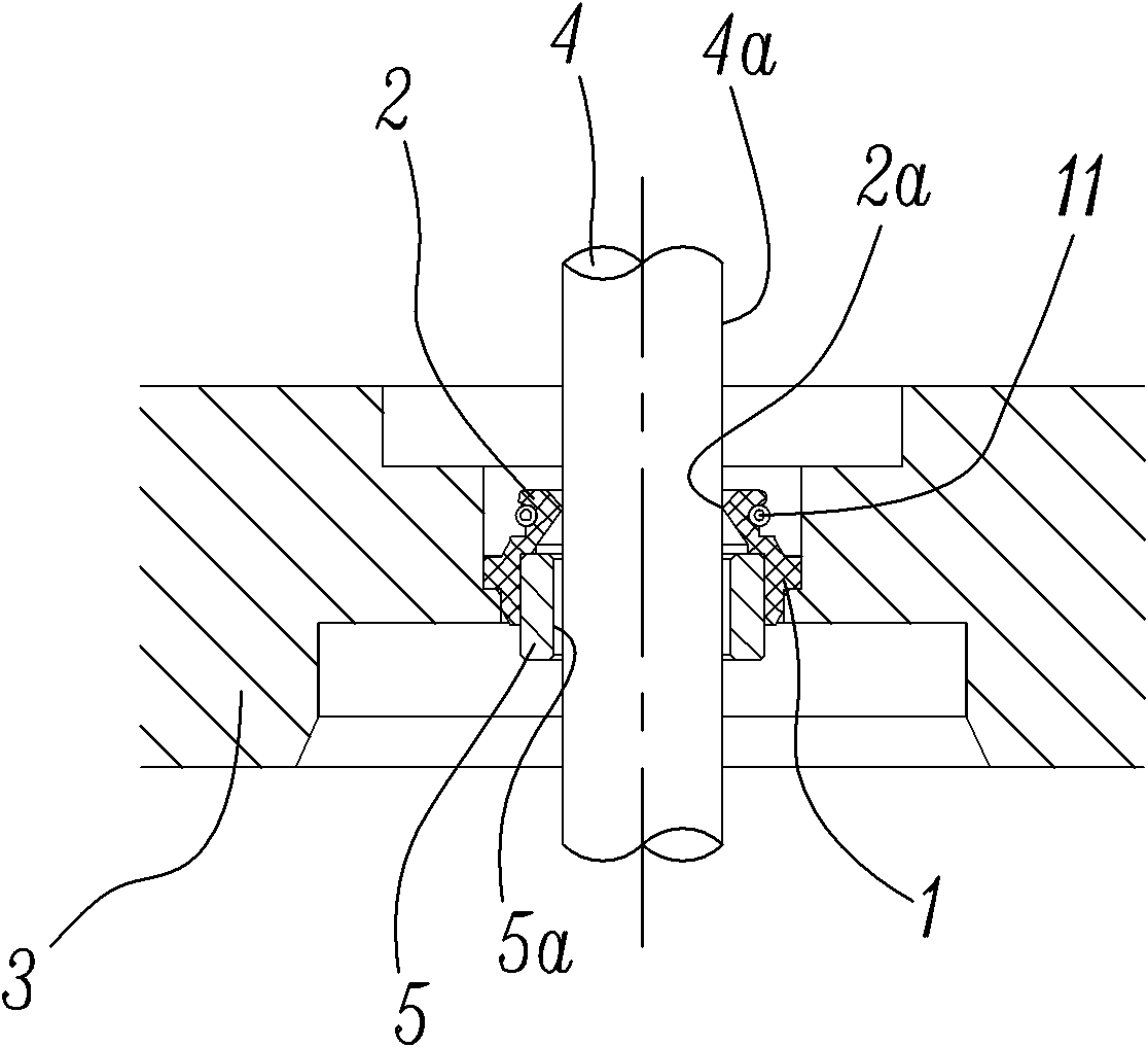
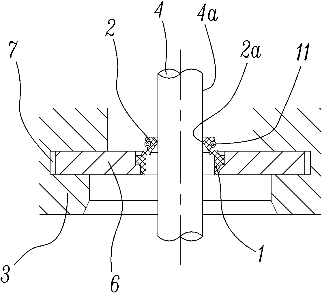
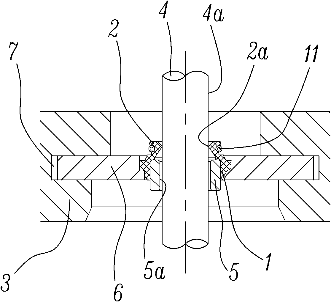
[0025] The present invention will be further described below with specific embodiment, see Figure 1-8 :

[0026] The shaft seal structure includes a shaft seal main body 1, a sealing lip 2, an end plate 3 and a moving rod 4, the sealing lip 2 is tightly connected with the shaft sealing main body 1 or the sealing lip 2 is integrally structured with the shaft sealing main body 1, and the sealing lip 2 has a closed-loop lip 2a, the moving rod 2 passes through the shaft seal main body 1 and the sealing lip 2, and the lip 2a of the sealing lip 2 is in dynamic sealing cooperation with the outer surface 4a of the shaft of the moving rod 4, the maximum of the present invention The feature is that it is provided with a floating guide sleeve 5 or / and a floating guide piece 6, wherein: 1) when only the floating guide sleeve 5 is provided, the outer surface of the floating guide sleeve 5 is matched with the shaft seal main body 1, and the moving rod 4 Through the inner hole 5a of the fl...


PUM


Abstract

The invention belongs to the field of mechanical engineering and relates to a shaft seal structure. The shaft seal structure comprises a shaft seal body, a seal lip, an end plate and a dynamic rod, wherein a floating guide sleeve or / and a floating guide vane is arranged on the shaft seal; the dynamic rod passes through the floating guide sleeve and is in clearance fit with the floating guide sleeve; the floating guide vane is in clearance fit with the end plate; and both the floating guide sleeve and the floating guide vane are connected with the shaft seal body hermetically. The shaft seal structure is a floating guide sleeve or floating guide vane structure; the floating guide sleeve and the floating guide vane can drive the shaft seal body and have certain displacement relative to the end plate; the floating guide sleeve is subjected to the shaking movement of the dynamic rod and the force generated by the shaking movement, the deformation range of the seal lip relative to that of a dynamic rod body is reduced, the circular degree of the opening of the seal lip and the distribution uniformity of tightening force of the opening attaching to the dynamic rod are increased, and thefollowing performance of the shaft seal body relative to the dynamic rod is increased due to the existence of the floating guide vane, so that the shaft seal can still keep excellent tightness even if the shaft seal is in vibration and swinging states.

Description

technical field [0001] The invention belongs to the field of mechanical engineering, and in particular relates to a shaft seal structure, more specifically to a shaft seal structure for sealing moving parts. Background technique [0002] There are a large number of motion pairs in the field of mechanical engineering, such as the valve and valve guide of the engine, the piston rod and end cover of the reciprocating oil cylinder and the reciprocating cylinder, the piston rod and cover plate of the linear reciprocating compressor, etc. These moving parts usually need to use Lubricating oil is used for lubrication. In order to prevent the lubricating oil from leaking out and prevent the outside atmosphere and dust from entering the machine, the shaft seal structure is often used to seal it. The shaft seal currently in use includes the shaft seal main body, sealing lip and elastic ring. The main body of the shaft seal is fastened on the end cover or cover plate, the reciprocating...

Claims


Application Information

Patent Timeline
IPC IPC(8): F16J15/16F16J15/32F16J15/3208F16J15/3232
Inventor 陈君立阮勤江耿爱农
Owner ZHEJIANG HONGYOU AIR COMPRESSOR MFG
Why Eureka
Try Eureka