
Mechanically-driven random speed change linear motion device

A technology of linear motion and mechanical transmission, applied in the direction of electromechanical devices, control mechanical energy, electric components, etc., can solve the problems of large volume, complex structural system, high failure rate, etc., achieve small space occupied by the mechanism, and solve complex structural systems , the effect of high degree of automation

Inactive Publication Date: 2011-01-05
郑庆各
View PDF0 Cites 1 Cited by
  • Summary
  • Abstract
  • Description
  • Claims
  • Application Information

AI Technical Summary

Problems solved by technology

The mechanical method generally needs to go through the gear transmission mechanism, the crank connecting rod mechanism or the rack and pinion mechanism. The pneumatic or hydraulic method requires not only the actuator cylinder or hydraulic cylinder, but also a stable air or hydraulic source. In addition, in order to To implement the above-mentioned linear motion mechanism, it is necessary to add a corresponding electrical control system. Therefore, there are defects such as complex structure system, large volume, high cost, and high failure rate.

Method used


Image

  • Mechanically-driven random speed change linear motion device
  • Mechanically-driven random speed change linear motion device

Examples


Embodiment Construction

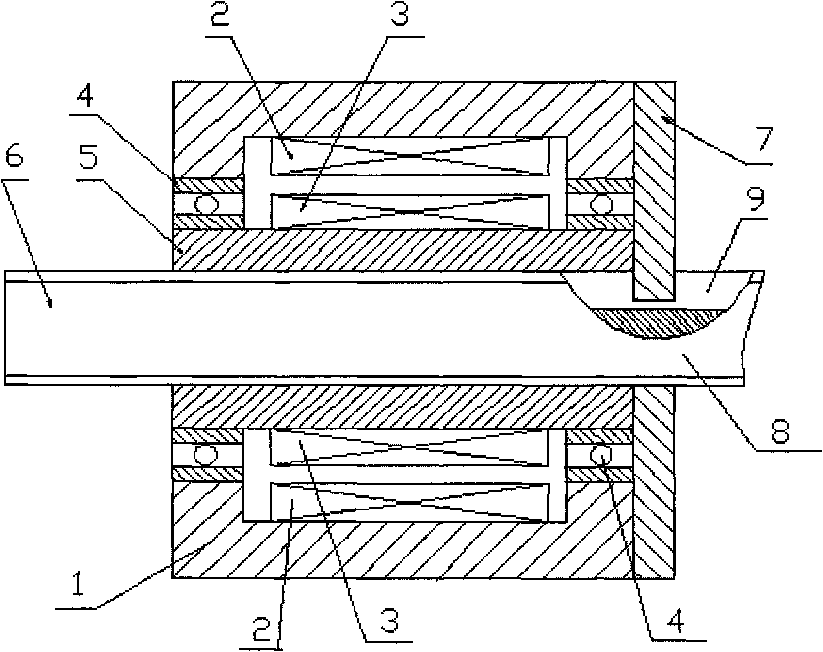
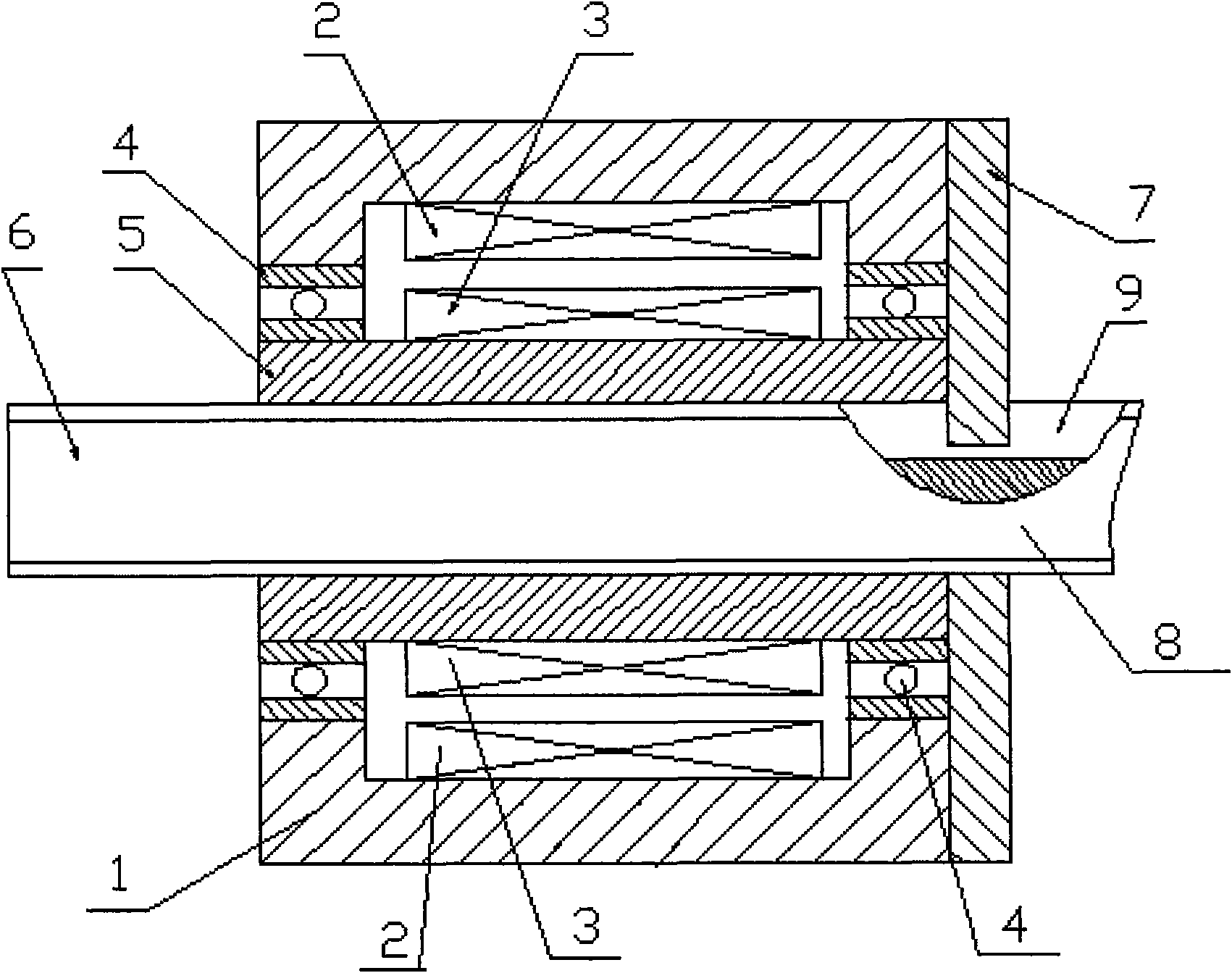
[0009] A variable frequency motor is composed of a base (1), a variable frequency coil winding (2), a rotor (3), a bearing (4), and a hollow shaft (5), and the hollow shaft (5) is located on the outer circle inside the base The fixed rotor (3) is installed, the hollow shaft (5) is installed on the support (1) through the bearing (4), and the internal thread of the corresponding specification is produced on the hollow inner circle of the hollow shaft (5), and the leading screw ( 6) on the outer circle of the hollow shaft, an external thread of the same specification as the hollow inner circle of the hollow shaft is produced, and the leading screw (6) is screwed into the internal thread of the hollow shaft (5) through the external thread on it, and the leading screw (6) ) is made on the outer circle of the chute (9) parallel to its axis, the middle of the stop plate (7) is a hole similar to the cross-sectional shape of the lead screw, and its protruding anti-rotation tongue (8) i...


PUM


Abstract

The invention discloses a mechanically-driven random speed change linear motion device. The device comprises a variable-frequency motor consisting of a machine base, a variable-frequency coil winding, a rotor, a bearing and a hollow shaft, wherein the excircle, positioned inside the machine base, of the hollow shaft is provided and fixed with the rotor; the hollow shaft is arranged on the machine base through the bearing; internal threads with a corresponding specification are manufactured on an hollow inner circle of the hollow shaft; external threads with the same specification as that of the hollow inner circle of the hollow shaft are manufactured on the excircle of a leading screw; the leading screw is screwed into the internal threads of the hollow shaft through the external threads thereon; a sliding chute parallel with the axial line of the excircle of the leading screw is manufactured on the excircle of the leading screw; the middle part of a stop plate is provided with a hole with a shape similar to that of the cross section of the leading screw, a protrudent rotation stopping tongue of the stop plate is buckled in the sliding chute of the leading screw to form a sliding fit; and the stop plate is arranged and fixed at one end of the machine base through bolts.

Description

technical field [0001] The invention relates to an arbitrary variable speed linear motion device, in particular to an arbitrary variable speed linear motion device with mechanical transmission. It belongs to the technical field of mechanical transmission. Background technique [0002] In the field of mechanical manufacturing and mechanical transmission technology, linear motion mechanisms are often used. At present, mechanical, pneumatic or hydraulic methods are mainly used to realize linear motion mechanisms. The mechanical method generally needs to go through the gear transmission mechanism, the crank connecting rod mechanism or the rack and pinion mechanism. The pneumatic or hydraulic method requires not only the actuator cylinder or hydraulic cylinder, but also a stable air or hydraulic source. In addition, in order to To implement the above-mentioned linear motion mechanism, it is necessary to add a corresponding electrical control system, so there are defects such as ...

Claims


Application Information

Patent Timeline
Patent Type & Authority Applications(China)
IPC IPC(8): H02K7/10
Inventor 郑庆各
Owner 郑庆各
Learn More