Dimmable light-emitting diode device used for reducing output ripple current and driving circuit thereof

A technology of light-emitting diodes and ripple current, applied in the field of light-emitting diode devices, can solve the problems of large current ripples of light-emitting diodes, overheating of light-emitting diodes, shortening service life, etc., to reduce output current ripples, increase capacitance, expand range effect

Inactive Publication Date: 2011-01-05
PHIHONG TECH CO LTD
View PDF5 Cites 29 Cited by
  • Summary
  • Abstract
  • Description
  • Claims
  • Application Information

AI Technical Summary

Problems solved by technology

The disadvantage of small output capacitance is that the current ripple output to the LED is large, and the large output current ripple

Method used


Image

  • Dimmable light-emitting diode device used for reducing output ripple current and driving circuit thereof
  • Dimmable light-emitting diode device used for reducing output ripple current and driving circuit thereof
  • Dimmable light-emitting diode device used for reducing output ripple current and driving circuit thereof

Examples


Embodiment Construction

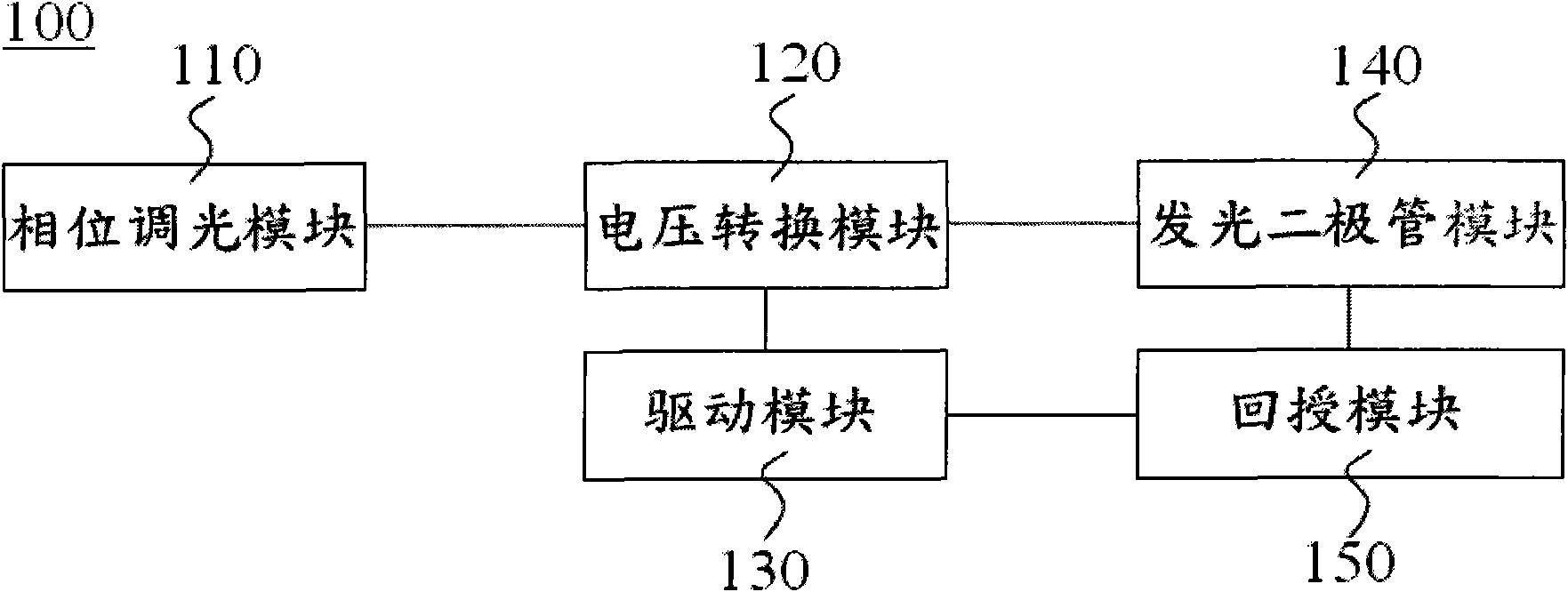
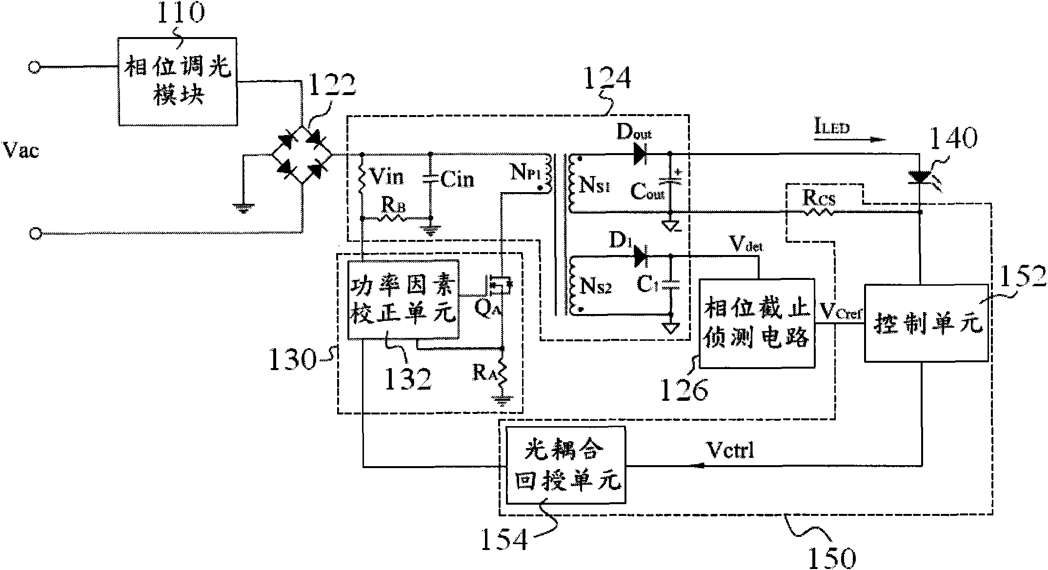
[0035] The present invention utilizes a light-emitting diode driver made on the basis of a single-stage high power factor flyback converter (Single stage PFC-Flyback converter) circuit, and controls the input current according to the amplitude and waveform of the mains voltage, which can greatly reduce the input current and the mains voltage. Phase distortion and waveform distortion between electric voltage and voltage, thereby improving power factor; reducing virtual power loss to achieve energy-saving effect.

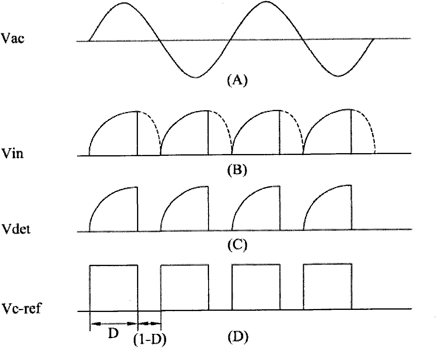
[0036] The light-emitting diode driving circuit utilized in the present invention utilizes a single-stage high power factor flyback converter circuit, and is applicable to a phase dimmer of commercial power to perform the function of dimming. Regardless of the leading edge or trailing edge phase angle (Leading edge or Trailing edge) of the input voltage signal is cut off by the phase dimmer, the output current of the LED driver will also be cut off in real time and in ...


PUM


Abstract

The invention discloses a dimmable light-emitting diode device used for reducing output ripple current, which comprises a light-emitting diode module, a phase tuning module, a voltage conversion module, a driver module and a feedback module. A flyback converter in the voltage conversion module is provided with a secondary clockwise winding and a phase cutoff sensing circuit so as to provide sensing voltage serving as an output current reference standard of the light-emitting diode module. The dimmable light-emitting diode device can make the flayback converter with the phase dimming function greatly increase output capacity and reduce the output ripple current, so that the light-emitting diode has stable light output. Therefore, the dimmable light-emitting diode device can prolong the service life of the dimmable light-emitting diode and prevent a light source flicker index from changing low.

Description

【Technical field】 [0001] The present invention relates to a light-emitting diode device, in particular to a dimmable light-emitting diode device for reducing output ripple current and its driving circuit. 【Background technique】 [0002] At present, the luminous brightness of traditional light bulbs is mainly determined by the magnitude of the current input to the light bulb. Therefore, the known technology has developed a light bulb with adjustable brightness. An AC dimmer is used to first phase-modulate the AC power input from the mains and then output an AC dimmer. With phase-modulated AC power, the user can control the AC dimmer by using the control components on the AC dimmer to adjust the phase of the AC power, so that the bulb can be illuminated by the phase-modulated AC power and its brightness can be controlled. [0003] The brightness of the bulb is determined according to the phase-modulated AC power output by the AC dimmer. If the voltage level obtained after pha...

Claims


Application Information

Patent Timeline
IPC IPC(8): H05B37/00H05B37/02H02M1/14
Inventor 朱崇仁陈怡静锺宏均
Owner PHIHONG TECH CO LTD
Why Eureka
Try Eureka