Continuous casting device and molten metal pouring nozzle

A continuous casting and liquid injection technology, which is applied in the field of continuous casting equipment, can solve the problems of increased cutting amount on the surface of the ingot and rupture of the ingot, and achieve the effect of preventing the fixation of the melt

Inactive Publication Date: 2011-01-05
SHOWA DENKO KK
View PDF8 Cites 3 Cited by
  • Summary
  • Abstract
  • Description
  • Claims
  • Application Information

AI Technical Summary

Problems solved by technology

[0006] However, if a large amount of lubricating oil is supplied, there is a problem that the ingot breaks (breakout) due to the excessively vaporized gaseous lubricating oil, or the excess lubricating oil contacts and reacts with the melt, and the reaction product ( Carbide) is involved in the ingot, the amount of cutting on the surface of the ingot increases, and the ingot becomes a defective product

Method used


Image

  • Continuous casting device and molten metal pouring nozzle
  • Continuous casting device and molten metal pouring nozzle
  • Continuous casting device and molten metal pouring nozzle

Examples


Embodiment 1、2

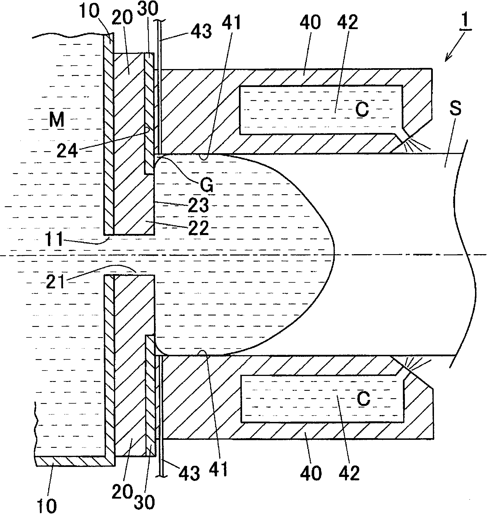
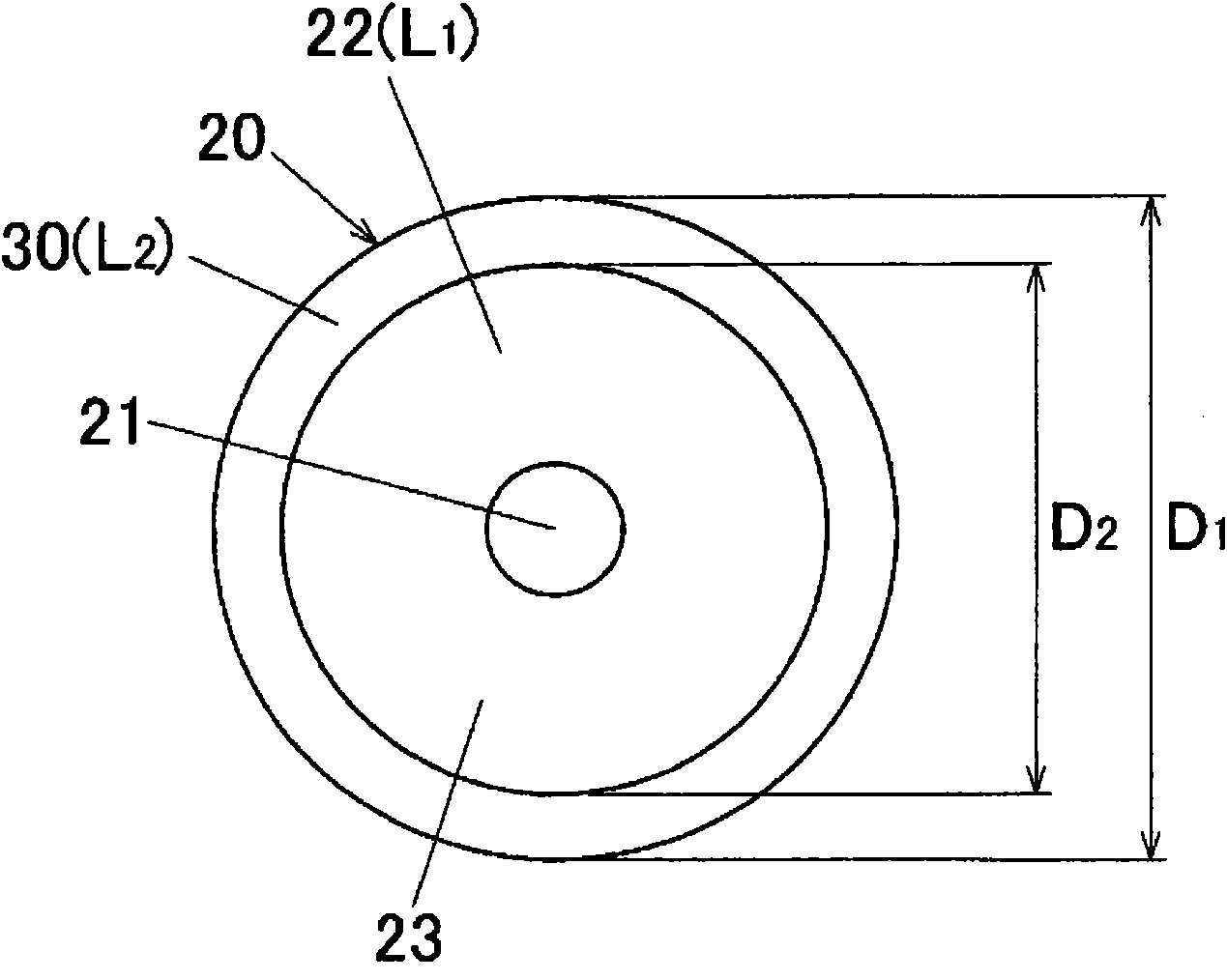
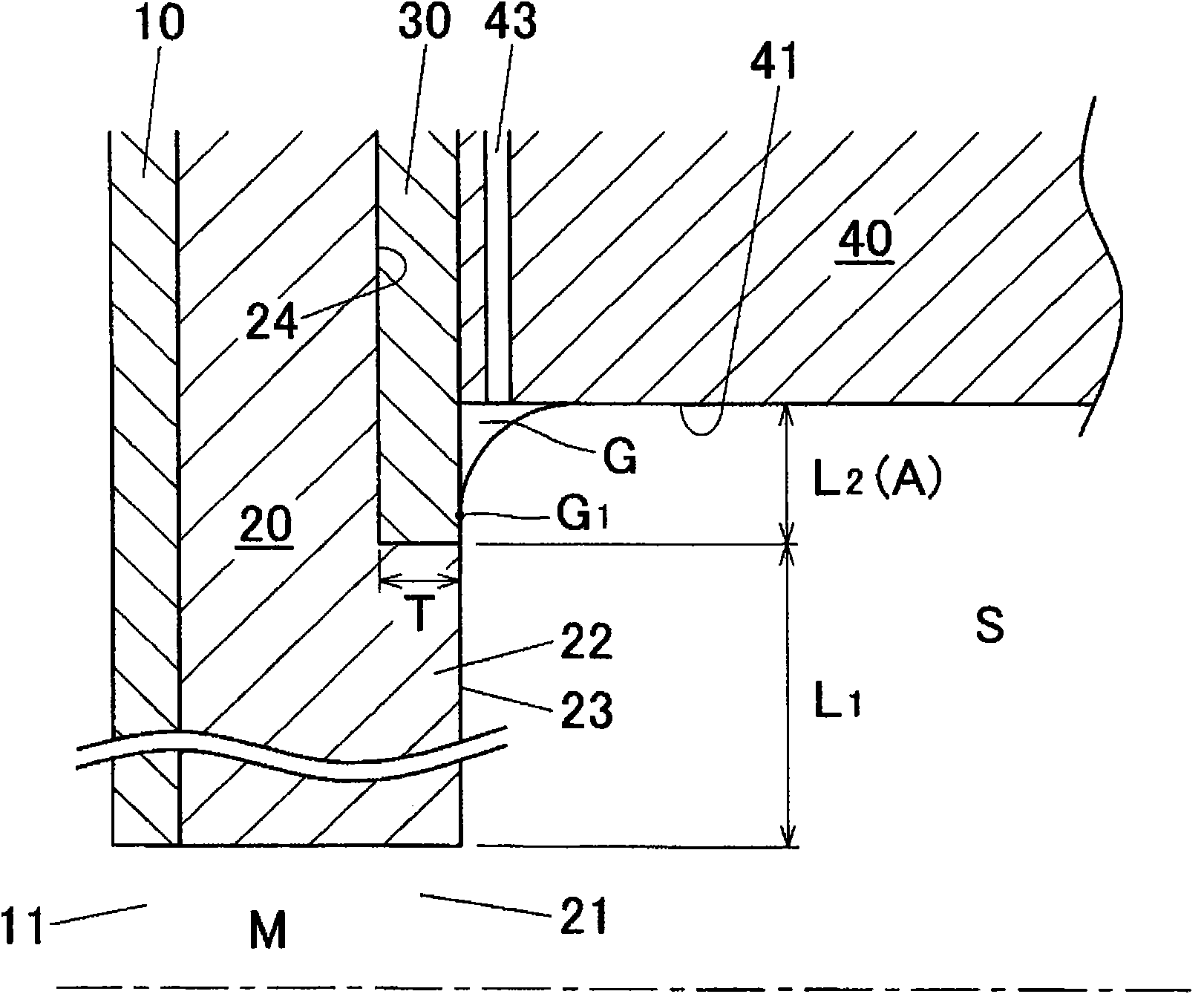
[0070] as reference figure 1 , Figure 2A , Figure 2B In this way, on the mold-side end surface 23 of the main body portion 22 of the injection nozzle 20, a graphite ring-shaped member 30 with a thickness T of 3 mm is arranged so that the protrusion A from the periphery of the forming hole 41 of the mold 40 is 3 mm or more. 2.2mm. In addition, the lubricating oil supply pipe 43 is opened in the forming hole 41 of the mold 40 to utilize the lubricating oil supplied to the mold 40 . Lubricating oil was supplied in the amount shown in Table 2.

Embodiment 3、4

[0072] as reference Figure 5 In this way, a sleeve 25 made of silicon nitride with a thickness of 1 mm is attached to the liquid injection passage 21 of the liquid injection nozzle 20, so that the vaporized lubricating oil does not leak from the liquid injection passage 21. The other configurations are the same as in Embodiment 1. , 2 are the same.

Embodiment 5、6

[0074] as reference Figure 6 In this way, the sleeve 45 made of graphite is caulked into the peripheral wall of the forming hole 41 of the mold 40 to facilitate the sliding of the ingot S in the mold 40 . The other constitutions are the same as those in Embodiments 1 and 2.


PUM


Abstract

A continuous casting device in which an end surface of a molten metal pouring nozzle can achieve good lubricating ability without an increase in the amount of lubricating oil, so that the continuous casting device can cast ingots having good casting surface quality for a long period of time. The continuous casting device (1) has the molten metal pouring nozzle (20) provided between a molten metal receiving section (10) and a mold (40). The pouring nozzle (20) has a tubular body (22) having a molten metal path (21) and made from a fire-resistant substance. A self-lubricating annular member (30) is placed on a mold-side end surface (23) of the body (22) so as to surround the molten metal pouring path (21).

Description

technical field [0001] The present invention relates to a continuous casting apparatus in which a liquid injection nozzle having a liquid injection path is interposed between a melt receiver and a mold, and an alloy melt in the melt receiver is supplied from the liquid injection channel to the mold to manufacture a metal casting rod. Background technique [0002] Figure 7 The structure of the conventional horizontal continuous casting apparatus 2 is shown. [0003] In the horizontal continuous casting apparatus 2 described above, a rod-shaped long ingot is produced from a molten metal through the following procedure. That is, the melt M in the melt receiver 10 passes through the outlet port 11, passes through the injection channel 21 of the injection nozzle 50 made of a refractory material, and then enters the substantially horizontal cylindrical mold 40. , where it is forced to cool, forming a solidified shell on the outer surface of the melt. Furthermore, the cooling wa...

Claims


Application Information

Patent Timeline
Patent Type & Authority Applications(China)
IPC IPC(8): B22D11/07B22D11/00B22D11/04B22D11/059B22D11/10
CPCB22D11/0475B22D11/04B22D11/059B22D11/07
Inventor 福田政志福岛政敏
Owner SHOWA DENKO KK
Why Eureka
Try Eureka