
Method for visualizing images and a device for performing the same

An image and pixel technology, applied in the field of video information imaging, can solve problems that are not suitable for visualizing three-dimensional images

Inactive Publication Date: 2011-01-05
弗拉基米尔・伊斯凡迪亚洛维奇・阿扎洛夫
View PDF9 Cites 4 Cited by
  • Summary
  • Abstract
  • Description
  • Claims
  • Application Information

AI Technical Summary

Problems solved by technology

[0009] The main disadvantage of the prior art method and prior art device solution closest to the claimed invention is that it is not suitable for visualizing three-dimensional images

Method used


Image

  • Method for visualizing images and a device for performing the same
  • Method for visualizing images and a device for performing the same

Examples


Embodiment Construction

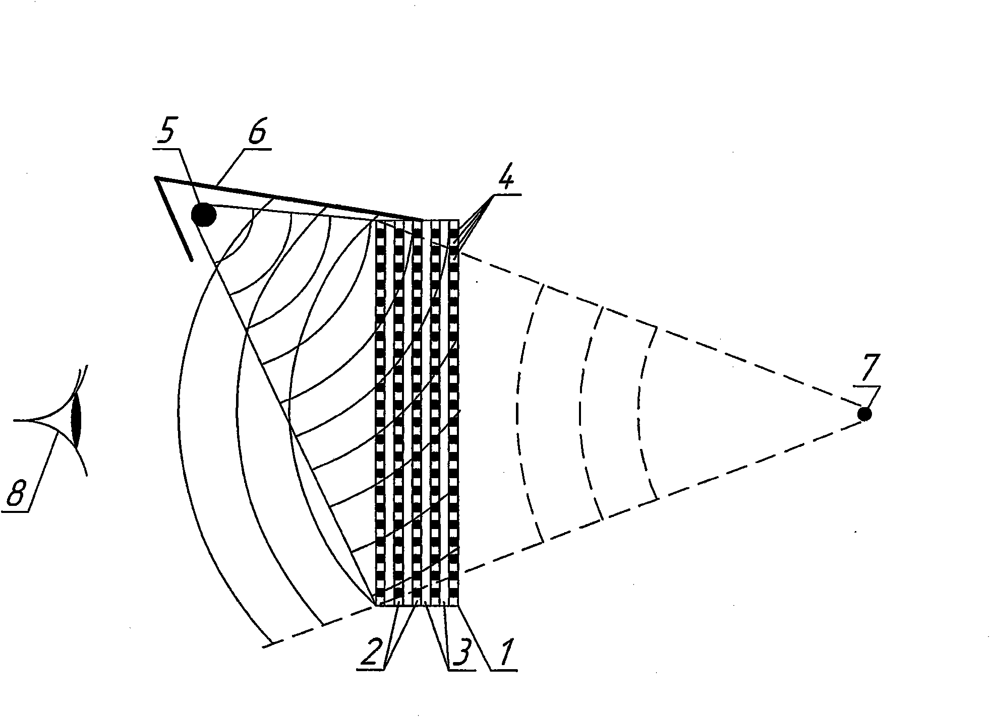
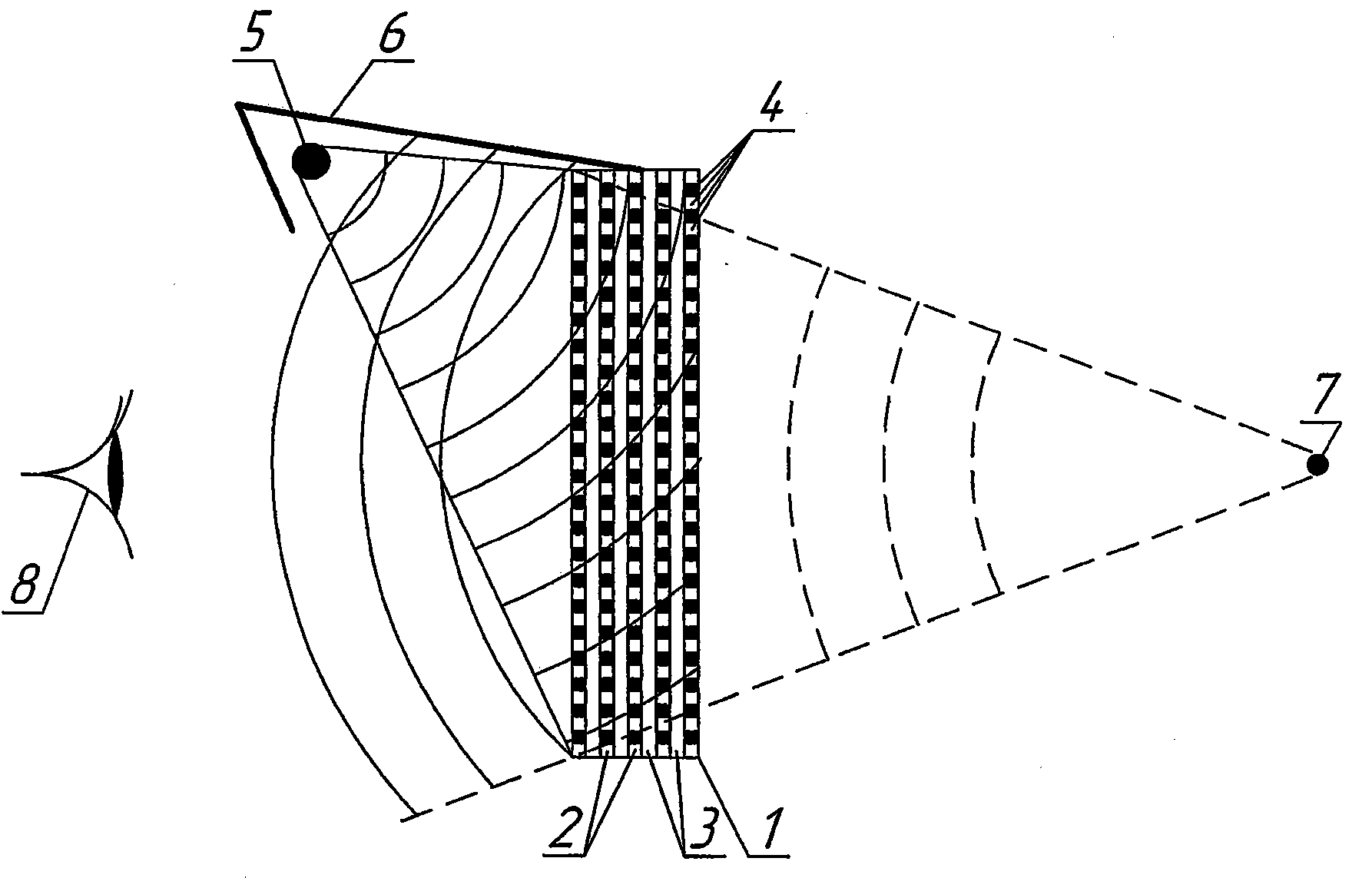
[0027] figure 1 Illustrated is a screen 1 which is a multilayer structure comprising spaced apart layers 2 of a material exhibiting an electro-optic effect, and a layer 3 of a material which is transparent to optical radiation and which does not exhibit an electro-optic effect , the layers capable of exhibiting the electro-optic effect are electrically insulated from each other and each of them is made into a matrix of electrically controlled elements or pixels 4 . The figure also shows a source of broadband optical radiation 5 facing the screen (facing the viewer) on the outside of the screen 1, and an element 6 mechanically connecting the source 5 to the screen. In order to facilitate the explanation of the concept of the present invention, the accompanying drawings also show a recoverable (observable) point light source 7 (in fact, any possible complex three-dimensional image element), and a mechanical coupling element 6 to prevent the observer's eyes from 8 faces the dire...


PUM


Abstract

The invention relates to information engineering and is used for visualising three-dimensional images. Said invention makes it possible to develop electrically controlled phase three-dimensional diffraction gratings and screens based thereon for displaying three-dimensional colour images. The inventive method involves simultaneously illuminating by a light beam a pixel array unit in which the arrays are positioned in parallel to each other, wherein the arrays are illuminated from the side, from which the image is visualised and a refraction factor is used as a variable optical characteristic of pixels in all said arrays. The device comprises a screen in the form of a multilayer structure which contains the layers of electro-optical effect material alternating with the layers of transparent material which is devoid of said effect. All the layers of the electro-optical effect material are electrically insulated from each other and each of which is made in the form of an array of electrically controlled pixel elements.

Description

technical field [0001] The invention relates to information technology, in particular to methods and devices for video information imaging, intended for the visualization of three-dimensional images. Background technique [0002] The methods and devices known in the prior art for visualizing dynamically changing stereoscopic (three-dimensional) images are all based on variants of the stereoscopic effect (see, for example: priority date of February 2006 by V.A. Ezhov et al. Russian Patent No. RU2,306,678, C1 on the 7th; and Russian Patent No. RU2,189,619, C1 with a priority date of January 10, 2001 proposed by V.S.Petrov et al. [0003] The main disadvantages of these and similar methods and the devices used to perform them are the inconvenience of viewing and the apparent distortions that occur during the transmission of the three-dimensional images. [0004] A method for recording a three-dimensional phase hologram and a device for carrying out the method have also been di...

Claims


Application Information

Patent Timeline
Patent Type & Authority Applications(China)
IPC IPC(8): G03H1/22
CPCG03H2227/06G03H2001/0484G03H2240/61G03H2225/22G03H2225/32G03H2001/2231G03H1/0402G03H2225/13G03H2222/24G03H1/2294G02F1/0322G03H2222/18G03H1/02G03H2222/23G03H2001/0224G02F2203/12
Inventor 弗拉基米尔·伊斯凡迪亚洛维奇·阿扎洛夫
Owner 弗拉基米尔・伊斯凡迪亚洛维奇・阿扎洛夫
Learn More