Apparatus on a flat card or roller card for setting the working spacing between the cylinder and one neighbouring roller

A carding machine and equipment technology, applied in fiber processing, textile and papermaking, deburring devices, etc., can solve problems such as contact between roller working elements, achieve fast closed-loop and open-loop control, flexibly respond to state changes, and quickly respond to state changes. Effect

Active Publication Date: 2014-12-24
TRUETZSCHLER GRP SE
View PDF6 Cites 0 Cited by
  • Summary
  • Abstract
  • Description
  • Claims
  • Application Information

AI Technical Summary

Problems solved by technology

This can lead to contact between the drum and the surrounding rollers and working elements

Method used


Image

  • Apparatus on a flat card or roller card for setting the working spacing between the cylinder and one neighbouring roller
  • Apparatus on a flat card or roller card for setting the working spacing between the cylinder and one neighbouring roller
  • Apparatus on a flat card or roller card for setting the working spacing between the cylinder and one neighbouring roller

Examples


Embodiment Construction

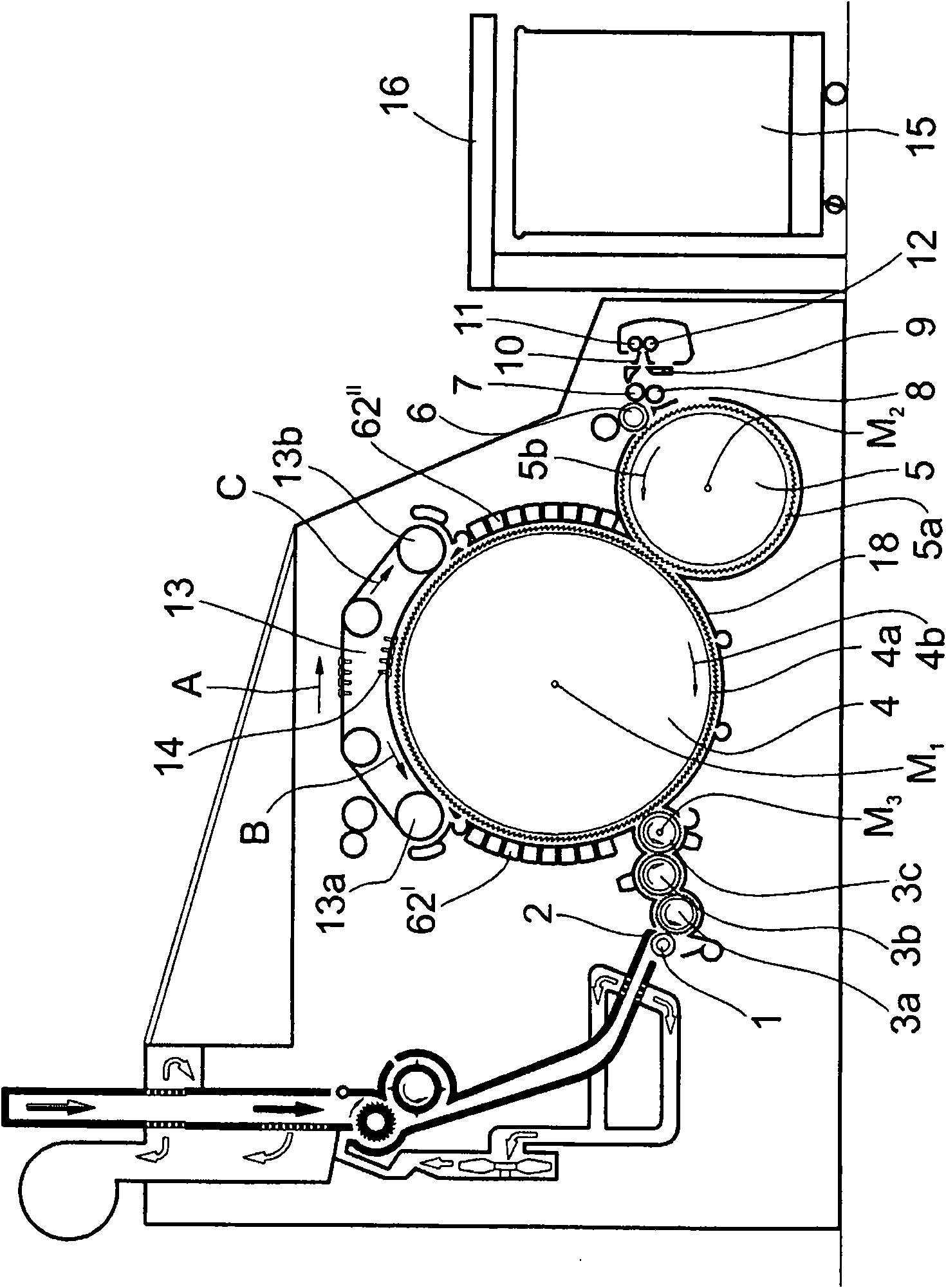
[0030] Attached figure 1 Shows a carding machine, such as a Triitzschler flat carding machine TC07, the carding machine has a feeding roller 1, feeding plate 2, licker rollers 3a, 3b, 3c, cylinder 4. Doffer 5, stripping roller 6, clamping roller 7, 8, cotton web guide 9, guide bar horn head 10, conveying roller 11, 12, cotton guide roller 13a, 13b with card top The rotating carding top 13, the carding cover 14, the can 15 and the coiling machine 16. The direction of rotation of the roller is indicated by a curved arrow. Reference symbol M 1 Indicates the center point (axis) of cylinder 4, reference symbol M 2 Indicates the center point of Doffer 5, reference symbol M 3 Indicates the center point of the licker roller 3c. Reference numeral 4a represents the card clothing, and reference numeral 4b represents the rotation direction of the cylinder 4. Reference numeral 5a denotes the card clothing, and reference numeral 5b denotes the direction of rotation of the doffer. Referenc...


PUM


Abstract

Apparatus on a flat card or roller card for setting the working spacing between a clothed cylinder (4, figure 2) and at least one clothed neighbouring roller (5), for example doffer and / or licker-in, comprises an adjustment device 28 operable by supplying and / or actively dissipating thermal energy. The device may move a doffer, licker-in or the main cylinder to compensate for changes in the working spacing caused by thermal or centrifugal effects. The adjustment device may comprise a peltier effect device 29 attached to an aluminium low mass tube to heat or cool the tube to effect the compensation. Alternatively a high volumetric expansion coefficient fluid (44, figure 5) may be heated or cooled using a peltier device (29) to cause activation of a spring biased piston (42). In an emergency a valve (60, figure 11) may be opened to release fluid. Alternatively, the cooling effect of compressed air may be used to cool the adjusting device. A closed loop control circuit may be used to regulate the energy supply of the peltier device.

Description

Technical field [0001] The present invention relates to a device on a flat carding machine or a roller carding machine, which is used to set the working distance between a cylinder with card clothing and at least one adjacent roller with card clothing. At least one adjacent roller is, for example, a doffer and / or a licker roller, and the cylinder and at least one adjacent roller are matched with each other at a small distance (working distance) between their cylindrical surfaces at the fiber transfer point, where as the reason As a result of dimensional changes caused by thermal expansion and / or centrifugal force, the working distance can be reset to a preset value, and an adjustment device for adjacent rollers can be provided, and the adjustment device can be operated by supplying heat energy. Background technique [0002] In the carding process, the number of fiber materials processed per unit time increases greatly, which requires higher speed or higher installed performance o...

Claims


Application Information

Patent Timeline
Patent Type & Authority Patents(China)
IPC IPC(8): D01G15/26D01G23/06
CPCD01G15/28
Inventor B·雅各布斯R·皮舍尔
Owner TRUETZSCHLER GRP SE
Why Eureka
Try Eureka