Dual-use vacuum relief valve

A safety valve and vacuum technology, applied in the direction of safety valve, lift valve, balance valve, etc., can solve the problems of single safety valve function, high precision requirements, complicated assembly and processing technology of two-way safety valve, etc., and achieve the effect of long service life.

Active Publication Date: 2013-04-24
上海远安流体设备科技有限公司
View PDF2 Cites 1 Cited by
  • Summary
  • Abstract
  • Description
  • Claims
  • Application Information

AI Technical Summary

Problems solved by technology

[0003] Therefore, the technical problem to be solved by the present invention lies in the problems existing in the prior art that the safety valve with simple structure has single function, the assembly and processing technology of the two-way safety valve is complex, and the precision requirements are high, so as to provide a simple structure and easy to process. Dual-purpose vacuum safety valve integrating positive pressure and negative pressure protection

Method used


Image

  • Dual-use vacuum relief valve
  • Dual-use vacuum relief valve

Examples


Embodiment 1

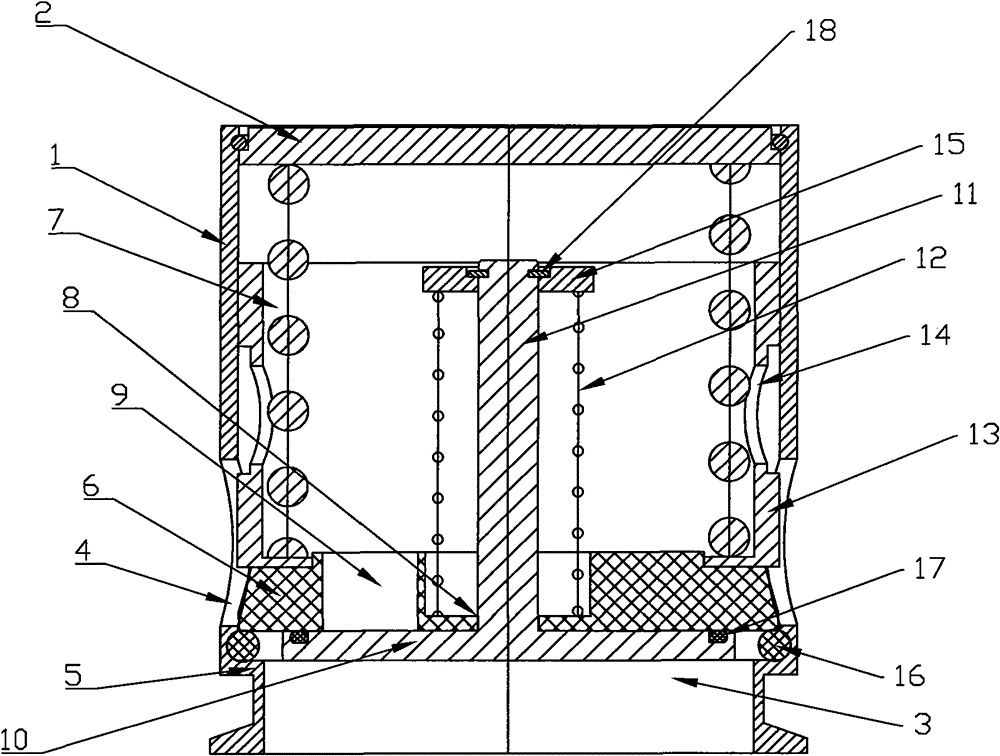
[0020] Dual-purpose vacuum safety valve of the present invention, as figure 1 Shown comprises a valve body, has a cylindrical housing 1 and a sealing cover plate 2 that seals one end of the cylindrical housing, a sealing ring is provided between the cylindrical housing 1 and the sealing cover plate 2, and the The other end of the cylindrical shell 1 forms a first air port 3, and a second air port 4 is formed on the side wall of the cylindrical shell 1, and the second air ports 4 are four, which are evenly distributed in the cylindrical shell 1, on the inner wall of the cylindrical shell 1 between the first gas port 3 and the second gas port 4, an inwardly protruding sealing boss 5 is formed, and the sealing boss 5 The sealing surface is facing the end provided with the sealing cover plate 2, the sealing surface of the sealing boss 5 here is a plane, in other embodiments it can be an upward slope or an arc, etc., as long as it can achieve the same The sealing of the first valv...

Embodiment 2

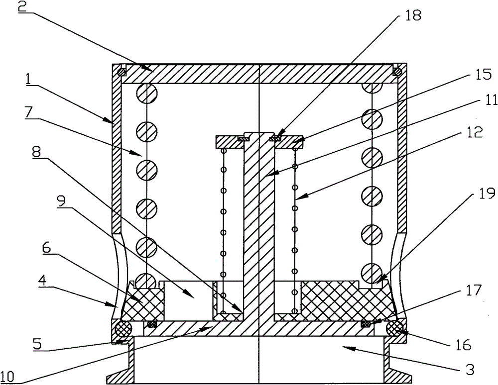
[0026] Dual-purpose vacuum safety valve of the present invention, as figure 2It includes a valve body and a valve core. The setting of the valve body is the same as in Embodiment 1. The valve core is also provided with a first valve plate assembly and a second valve plate assembly. The difference is that there is no cylindrical spring support on the top of the first valve plate. Instead, an annular groove 19 is provided on the upper surface of the first valve plate near the edge, and the first bias spring is installed on the sealing cover plate 2 and the annular groove 19 on the edge of the first valve plate 6 between. A sealing ring 16 is provided between the sealing boss 5 and the lower bottom surface of the first valve plate 6 . An annular groove is provided on the upper surface of the second valve plate 10 close to the outer edge, and a sealing ring 17 is arranged in the annular groove. The material of the first valve plate is polytetrafluoroethylene.

[0027] The work...


PUM


Abstract

A dual-use vacuum relief valve comprises a valve body and a spool, wherein the valve body is provided with a cylindrical shell and a sealing cover plate; a first gas port is formed on the other end of the cylindrical shell, a second gas port is formed on the side wall of the cylindrical shell, a sealing boss is formed on the inner wall of the cylindrical shell and between the two gas ports; the spool comprises a first valve plate component and a second valve plate component; the first valve plate component contains a first valve plate and a first bias spring; a guide hole and a vent hole are formed on the first valve plate; the second valve plate component contains a second valve plate and a second bias spring, the center of the second valve plate is fixedly connected with a guide post; and the second gas port is near the edge of the first valve plate. The invention has the advantages of simple structure and convenient processing and assembling.

Description

technical field [0001] The invention relates to a double-purpose vacuum safety valve. Specifically, it is a dual-purpose vacuum safety valve with simple structure and easy processing. Background technique [0002] The safety valve is a valve body that can automatically open and close according to the working pressure. It is generally installed on the equipment or pipeline of the closed system to protect the safety of the system. When the pressure in the equipment or pipeline of the closed system exceeds or falls below the specified value, the safety valve will automatically open to release or increase pressure in time to ensure that the medium pressure in the equipment and pipeline is within the specified value and prevent accidents. Patent document CN2132052Y discloses a vacuum air safety valve, which is composed of a tee, a valve stem, a bracket, a return spring, etc. The other two ends of the tee are respectively installed on the air pipeline to control the pressure in t...

Claims


Application Information

Patent Timeline
Patent Type & Authority Patents(China)
IPC IPC(8): F16K17/04F16K1/36F16K1/46
Inventor 项少聪
Owner 上海远安流体设备科技有限公司
Why Eureka
Try Eureka