Double-separation type fluidized bed slag cooler

A slag cooler and sorting technology, which is applied to fluidized bed combustion equipment, fuel burning in a molten state, combustion type, etc., can solve the problems of large operating air volume, low water cooling ratio, and large proportion of bottom slag and coarse slag, etc. Achieve the effect of reducing operating air volume, improving adaptability, and improving operating safety and reliability

Inactive Publication Date: 2011-01-12
CHONGQING UNIV
View PDF6 Cites 18 Cited by
  • Summary
  • Abstract
  • Description
  • Claims
  • Application Information

AI Technical Summary

Problems solved by technology

[0003] However, as the coal quality of CFB power plant boilers is getting worse and worse, the proportion of coarse slag in the bottom slag becomes larger, resulting in the original patented technology running too much air volume and low water cooling ratio in practical applications, so it

Method used


Image

  • Double-separation type fluidized bed slag cooler
  • Double-separation type fluidized bed slag cooler
  • Double-separation type fluidized bed slag cooler

Examples


Embodiment 1

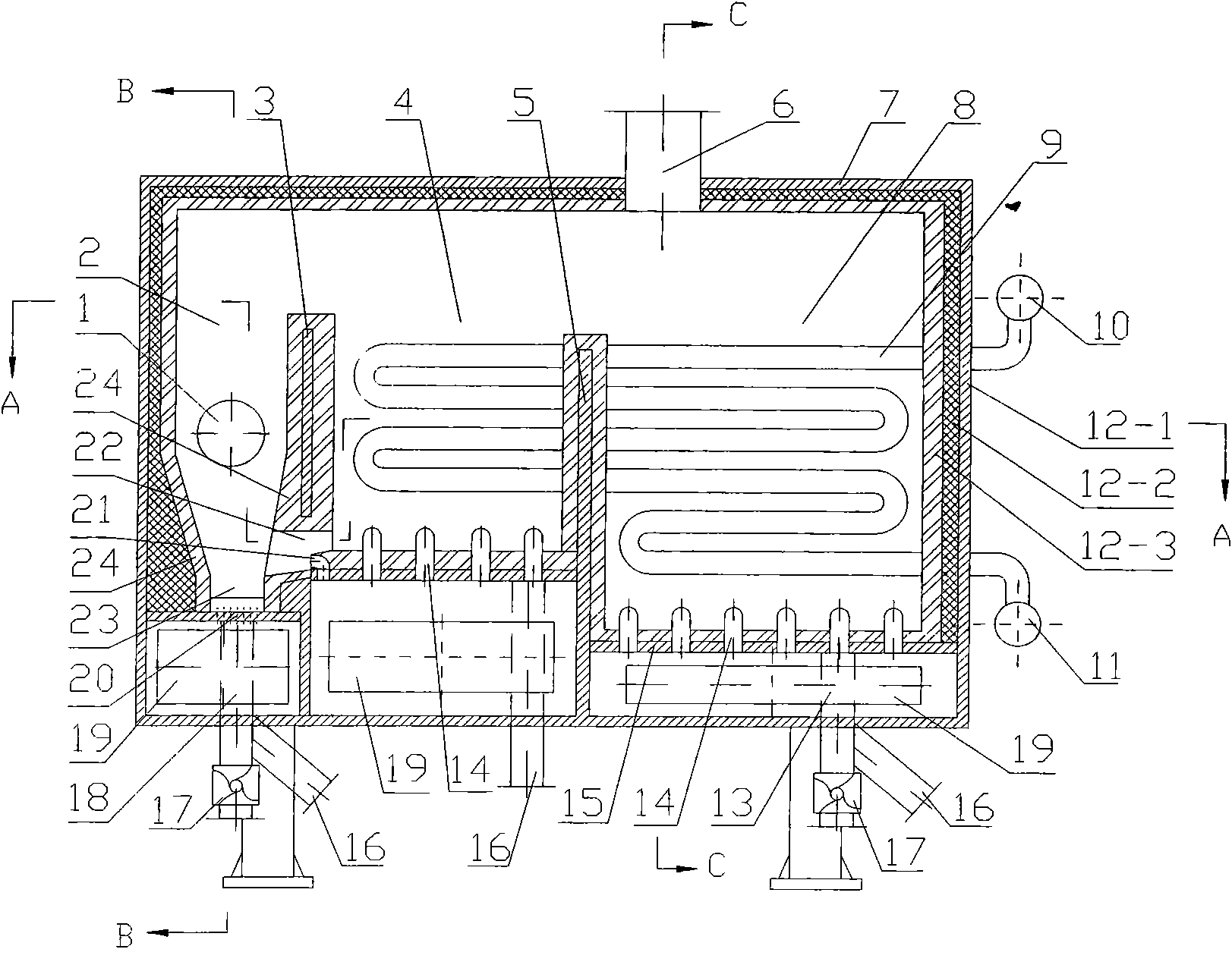
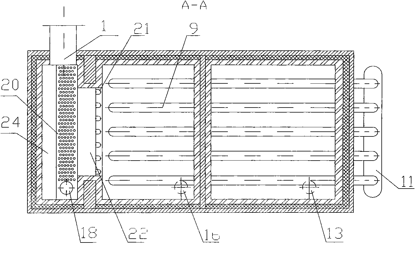
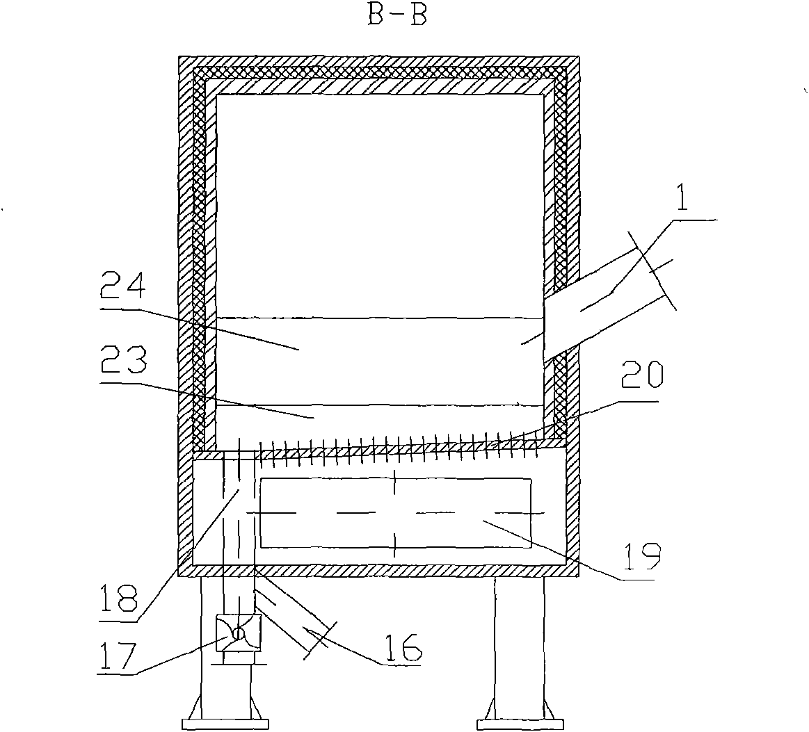
[0021] A kind of double sorting type fluidized bed slag cooler of the present embodiment such as figure 1 , figure 2 , image 3 and Figure 4As shown, the frame 12-1 of the main body 7 of the slag cooler is welded into a square body by steel plates, angle steels, and channel steels, and the inner side of the frame 12-1 is laid with thermal insulation materials and refractory materials successively. The thermal insulation layer 12-2 and the refractory layer 12-3 , the interior of the main body 7 of the slag cooler is arranged with a first partition wall 3 and a second partition wall 5, and the first partition wall 3 and the second partition wall 5 divide the internal space of the main body 7 of the slag cooler into three cooling chambers whose upper part communicates , the cooling bin at the left end is the sorting bin 2, the cooling bin in the middle is the circulation bin 4, and the cooling bin at the right end is the water cooling bin 8; independent air chambers 19 are se...

Embodiment 2

[0023] A combined double-separation fluidized bed slag cooler in this embodiment is as follows: Figure 5 , Figure 6 and Figure 7 As shown, when the design output is relatively large, a double-separation type fluidized bed slag cooler of the above-mentioned embodiment 1 is used as an independent module, consisting of 3 (or more, Figure 5 , Figure 6 and Figure 7 It is composed of 3) modules connected in series. Starting from the side where the slag feed pipe 1 is located, there are first-level modules, second-level modules and third-level modules in sequence. At this time, an inter-group partition wall 25 is installed between the corresponding cooling bins of the modules at all levels. For the sorting bin 2, the partition wall 25 between groups completely separates the upper part of the adjacent module sorting bin 2, and keeps the lower part connected, which can not only ensure that the coarse slag can be smoothly discharged from the slag cooler, but also prolong the ...


PUM


Abstract

The invention relates to a double-separation type fluidized bed slag cooler which comprises a main body (7), an air chamber (19), a slag circulating channel (22) and the like, wherein a first separation wall (3) and a second separation wall (5) are arranged in the main body (7) of the slag cooler and separate the inner space of the main body (7) of the slag cooler into 3 cooling bins (a separation bin (2), a circulating bin (4) and a water cooling bin (8)) the upper parts of which are communicated with each other; the first separation wall (3) is arranged between the separation bin (2) and the circulating bin (4); the bottom of the first separation wall (3) is provided with the slag circulating channel (22); and the slag circulating channel (22) is in a cascade plate structure. By carrying out two-stage separation on the bottom slag and arranging a slag circulating cooling loop between the separation bin (2) and the circulating bin (4), the invention reduces the air quantity for operation, enhances the adaptability to the particle size distribution of the boiler slag, increases the water cooling proportion and enhances the operation safety and reliability of the slag cooler.

Description

technical field [0001] The invention belongs to auxiliary equipment for circulating fluidized bed boilers, in particular to a slag cooling device for circulating fluidized bed boilers, which is suitable for cooling the slag of circulating fluidized bed boilers. Background technique [0002] Large-scale circulating fluidized bed is the most commercialized clean coal combustion technology in the world today, and it is developing rapidly in the direction of high-parameter large-scale. As the key auxiliary equipment of CFB boiler, the operation of slag cooler is directly related to the continuous safe and economical operation of CFB boiler. In recent years, due to the increasingly tight supply of coal, problems such as the complexity and changeability of the incoming coal of CFB power plant boilers in my country, poor coal quality, and unqualified coal preparation systems directly lead to the unsatisfactory operation of the traditional fluidized bed slag cooler currently used in...

Claims


Application Information

Patent Timeline
IPC IPC(8): F23C10/24
Inventor 卢啸风甘露曾兵
Owner CHONGQING UNIV
Why Eureka
Try Eureka