
Automatic assembly welding forming system of vehicle circuit breaker

An automatic assembly and breaker technology, applied in the direction of circuits, electric switches, electrical components, etc., can solve the problems of high scrap rate, poor process stability, complicated procedures, etc., and achieve the improvement of processing yield, low labor cost, and labor saving. Effect

Active Publication Date: 2012-05-30
AEROSPACE HI TECH HLDG GROUP
View PDF0 Cites 0 Cited by
  • Summary
  • Abstract
  • Description
  • Claims
  • Application Information

AI Technical Summary

Problems solved by technology

[0003] In order to solve the shortcomings of low precision, complicated procedures, high cost, high scrap rate, low efficiency and poor process stability in the process of metal sheet and base welding and torsion forming in the current manufacturing of circuit breakers for vehicles, the present invention proposes An automatic assembly and welding forming system for vehicle circuit breakers

Method used


Image

  • Automatic assembly welding forming system of vehicle circuit breaker
  • Automatic assembly welding forming system of vehicle circuit breaker

Examples


specific Embodiment approach 1

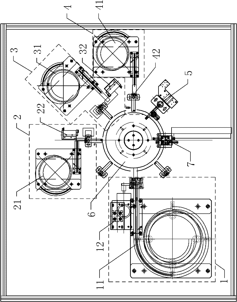
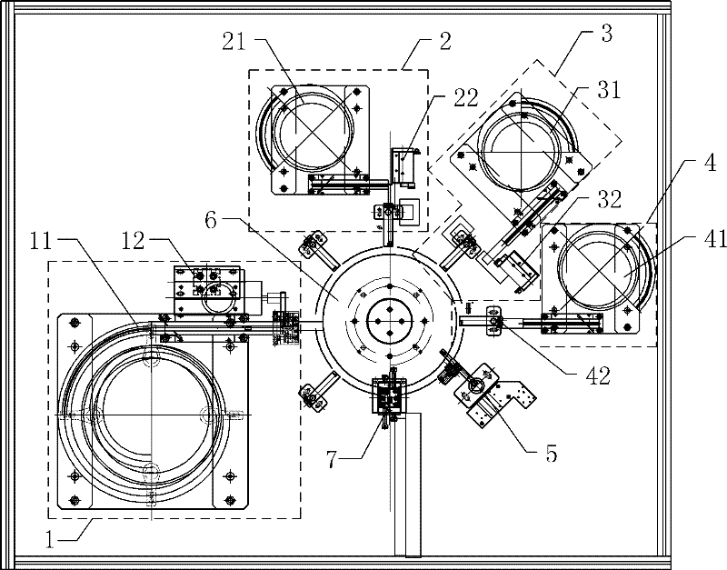
[0014] Specific implementation mode one: combine figure 1 Describe this embodiment, this embodiment includes a base feeding unit 1, a rivet riveting unit 2, a static contact welding unit 3, a metal sheet welding unit 4, a twist angle unit 5, an electronic indexing plate 6 and a handling and sorting robot 7;

[0015] On the circumferential direction of the upper surface of the electronic indexing plate 6, there are eight positions of fixed workpieces evenly distributed, with the electronic indexing plate 6 as the center, the position of each fixed workpiece is correspondingly provided with one on the outside of the electronic indexing plate 6 There are eight stations in total; during the rotation of the electronic indexing plate 6 itself, the position of any fixed workpiece on the electronic indexing plate 6 can correspond to each station respectively;

[0016] The first station is provided with a base feeding unit 1; the base feeding unit 1 includes a base supply vibrating pla...

specific Embodiment approach 2

[0022] Specific implementation mode two: combination figure 1 Describe this embodiment, the difference between this embodiment and the specific embodiment is that it also includes a base detection unit 8, the base detection unit 8 is arranged on the second station, and the base detection unit 8 is a photosensitive sensor for detecting electronic graduations Whether there is a base on the position of the fixed workpiece on the disk 6 corresponding to the second station. Other compositions and connection methods are the same as those in Embodiment 1.

specific Embodiment approach 3

[0023] Specific implementation mode three: combination figure 1 Describe this embodiment. The difference between this embodiment and the specific embodiment is that it also includes a component detection unit 9, which is arranged on the eighth station. The component detection unit 9 is a photosensitive sensor for detecting electronic graduations. Whether there is a base on the position of the fixed workpiece corresponding to the above-mentioned eight stations on the disk 6 . Other compositions and connection methods are the same as those in Embodiment 1.


PUM


Abstract

The invention discloses an automatic assembly welding forming system of a vehicle circuit breaker, which relates to the automatic assembly welding forming system and solves the defects of low precision, complicated procedure, high cost, high reject rate, low efficiency and poor process stability for the procedures of welding a metal sheet and a base and reversely forming and the like in the manufacture of the traditional vehicle circuit breaker. Eight positions of fixing a work-piece are uniformly distributed on the circumferential direction of the upper surface of an electronic graduated disk, and a station is correspondingly arranged at the outer part of each position with the electronic graduated disk as a center; any position of fixing the work-piece on the electronic graduated disk can respectively correspond to each station in the process of the electronic graduated disk rotating a circle per se; and a base feeding unit, a rivet riveting unit, a fixed contact welding unit, a metal sheet welding unit, a torsional angle unit and a conveying and separating manipulator are sequentially located on a first station, a third station, a fourth station, a fifth station, a sixth station and a seventh station. According to the invention, processing efficiency and processing finished product rate are remarkably enhanced and a great deal of manpower is saved.

Description

technical field [0001] The invention relates to an automatic assembly, welding and forming system, in particular to an automatic assembly, welding and forming system used in the manufacture of automotive circuit breakers. Background technique [0002] The manufacturing process of the existing vehicle circuit breaker is cumbersome, and there are many manual operations, so it is difficult to guarantee the consistency of the product. Manual operation is difficult to avoid waste products due to human factors. Moreover, in the existing manufacturing process, there is still a situation that each process equipment is independent in the cumbersome process. In this case, each equipment needs to be controlled separately, and cannot cooperate with each other, and the reject rate of the produced products is also high. Moreover, each independent device requires a separate site and personnel, which leads to a large production site and high labor costs (12 people for a single line). The a...

Claims


Application Information

Patent Timeline
Patent Type & Authority Patents(China)
IPC IPC(8): H01H11/00B23K31/02
Inventor 傅海林吕端秋马杰李岩刘振新
Owner AEROSPACE HI TECH HLDG GROUP
Learn More