Distributed base station

A distributed base station and baseband processing technology, applied in electrical components, wireless communication, network planning, etc., can solve problems such as increasing the number of cascades

Active Publication Date: 2011-01-12
COMBA TELECOM SYST CHINA LTD
View PDF3 Cites 14 Cited by
  • Summary
  • Abstract
  • Description
  • Claims
  • Application Information

AI Technical Summary

Problems solved by technology

While maintaining the advantages of traditional distributed base stations, it solves the problem of rising noise and reduc...

Method used


Image

  • Distributed base station
  • Distributed base station
  • Distributed base station

Examples


Embodiment 1

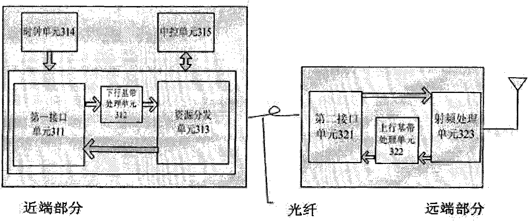
[0033] see image 3 , is a schematic structural diagram of the distributed base station of the present invention.

[0034] Such as image 3 As shown, the distributed base station includes a near-end part and a remote part; the near-end part includes a first interface unit 311, a downlink baseband processing unit 312, a resource distribution unit 313, a clock unit 314 and a central control unit 315; the remote part It includes a second interface unit 321 , an uplink baseband processing unit 322 and a radio frequency processing unit 323 .

[0035] In the proximal portion:

[0036] The first interface unit 311 receives a downlink signal from another network element and outputs it to the downlink baseband processing unit 312; and receives an uplink signal from the resource distribution unit 313 and outputs it to other network elements;

[0037] The downlink baseband processing unit 312 performs baseband processing on the downlink signal from the first interface unit 311 and out...

Embodiment 2

[0048] see Figure 4 , is a specific implementation manner when distributed base stations are cascaded at the remote end.

[0049] In this embodiment, one near-end part is serially cascaded with multiple far-end parts. The distal part 1 is directly connected to the proximal part through an optical fiber, the distal part 2 is connected to the proximal part via the distal part 1, the distal part 3 is connected to the proximal part via the distal parts 1 and 2, and so on.

[0050] In the remote cascading mode, the remote part 1 to the remote part N are all configured as the same cell.

[0051] In the remote cascading mode, the remote parts can be connected by optical fibers, network cables, or other media.

[0052]In this specific embodiment, since all the remote parts are set as the same cell, no signal switching will occur in the coverage area of ​​all the remote parts, which greatly improves the network performance in the high-speed railway operating environment. Similar wi...

Embodiment 3

[0054] see Figure 5 , is another specific implementation manner when the distributed base stations are cascaded at the remote end.

[0055] In this embodiment, the difference from the solution in the second embodiment above is that not all remote parts are configured as the same cell.

[0056] In the remote cascading method described above, when the capacity demand is not high, all remote parts are configured as the same cell, that is, Figure 4 The embodiment shown; when the capacity requirement is high, the remote part is configured as multiple cells.

[0057] In the multi-cell configuration method, only one remote part can be configured in one cell, or multiple remote parts can be configured in one cell. How to use this cross configuration method should be determined according to the situation of the project site.

[0058] In the remote cascading method, when the capacity requirement increases, the processing capability of the near-end part needs to be upgraded at the sa...


PUM


Abstract

The invention relates to a base station technique and provides a distributed base station. The distributed base station comprises a near-end part and a far-end part, wherein the near-end part comprises a first interface unit, a downlink baseband processing unit, a resource distributing unit, a clock unit and a central control unit; the far-end part comprises a second interface unit, an uplink baseband processing unit and a radio frequency processing unit; the near-end part is connected with the far-end part through optical fibers. On one hand, the distributed base station solves the problem of background noise lifting in the conventional network under the condition of maintaining the advantages of the traditional distributed base station so as to increase the far-end cascade number; and on the other hand, the distributed base station has the advantages of reducing the consumption of line circuit resources, not greatly increasing networking cost, reducing the complexity of the design of the far-end part and realizing the balance between the properties and the cost.

Description

technical field [0001] The invention relates to the technical field of mobile communication, in particular to a distributed base station. Background technique [0002] In the wireless cellular communication system, the base station is an important part of the whole system. Its function mainly communicates with other network elements such as the base station controller through the ground interface, and communicates with the user terminal through the air interface. [0003] In a traditional base station, the indoor part and the outdoor part are connected by cables. Because the loss of the cable is relatively large, it is easy to cause waste of resources; and the traditional base station is usually large and heavy, and the site selection and installation are relatively complicated. [0004] In order to solve the above problems, the industry has proposed a BBU+RRU distributed base station design method, which has gradually become the mainstream. A distributed base station usua...

Claims


Application Information

Patent Timeline
IPC IPC(8): H04W16/26H04W88/08
Inventor 张远见张跃军邓世群牛晨曦
Owner COMBA TELECOM SYST CHINA LTD
Why Eureka
Try Eureka