Distributed base station
A distributed base station and baseband processing technology, applied in electrical components, wireless communication, network planning, etc., can solve problems such as increasing the number of cascades
- Summary
- Abstract
- Description
- Claims
- Application Information
AI Technical Summary
Problems solved by technology
Method used
Image
Examples
Embodiment 1
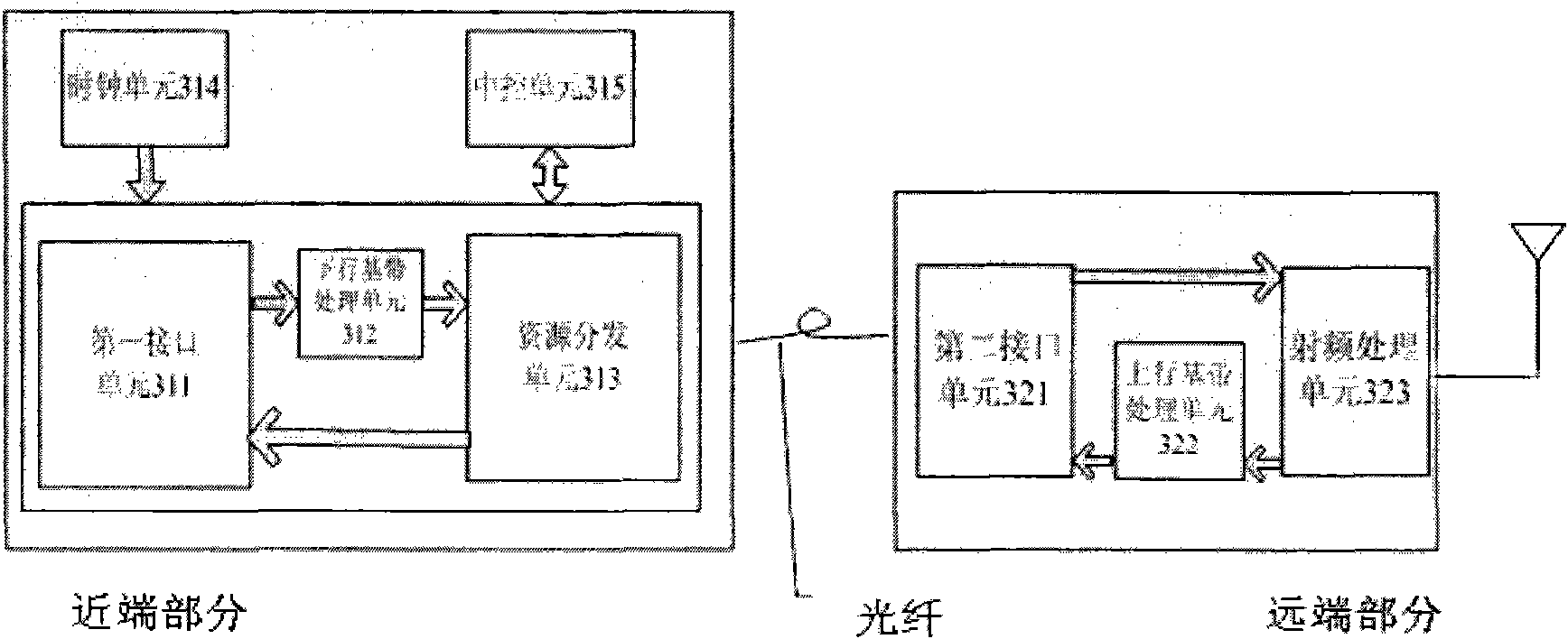
[0034] see image 3 , is a schematic structural diagram of the distributed base station of the present invention.
[0035] Such as image 3 As shown, the distributed base station includes a near-end part and a remote part; the near-end part includes a first interface unit 311, a downlink baseband processing unit 312, a resource distribution unit 313, a clock unit 314 and a central control unit 315; the remote part It includes a second interface unit 321 , an uplink baseband processing unit 322 and a radio frequency processing unit 323 .
[0036] In the proximal portion:
[0037] The first interface unit 311 receives a downlink signal from another network element and outputs it to the downlink baseband processing unit 312; and receives an uplink signal from the resource distribution unit 313 and outputs it to other network elements;
[0038] The downlink baseband processing unit 312 performs baseband processing on the downlink signal from the first interface unit 311 and out...
Embodiment 2
[0049] see Figure 4 , is a specific implementation manner when distributed base stations are cascaded at the remote end.
[0050] In this embodiment, one near-end part is serially cascaded with multiple far-end parts. The distal part 1 is directly connected to the proximal part through an optical fiber, the distal part 2 is connected to the proximal part via the distal part 1, the distal part 3 is connected to the proximal part via the distal parts 1 and 2, and so on.
[0051] In the remote cascading mode, the remote part 1 to the remote part N are all configured as the same cell.
[0052] In the remote cascading mode, the remote parts can be connected by optical fibers, network cables, or other media.
[0053] In this specific embodiment, since all the remote parts are set as the same cell, no signal switching will occur in the coverage area of all the remote parts, which greatly improves the network performance in the high-speed railway operating environment. Similar wid...
Embodiment 3
[0055] see Figure 5 , is another specific implementation manner when the distributed base stations are cascaded at the remote end.
[0056] In this embodiment, the difference from the solution in the second embodiment above is that not all remote parts are configured as the same cell.
[0057] In the remote cascading method described above, when the capacity demand is not high, all remote parts are configured as the same cell, that is, Figure 4 The embodiment shown; when the capacity requirement is high, the remote part is configured as multiple cells.
[0058] In the multi-cell configuration method, only one remote part can be configured in one cell, or multiple remote parts can be configured in one cell. How to use this cross-over configuration method should be determined according to the situation of the project site.
[0059] In the remote cascading method, when the capacity requirement increases, the processing capability of the near-end part needs to be upgraded at t...
PUM
 Abstract
Description
Claims
Application Information
 - R&D
- Intellectual Property
- Life Sciences
- Materials
- Tech Scout
- Unparalleled Data Quality
- Higher Quality Content
- 60% Fewer Hallucinations
Browse by: Latest US Patents, China's latest patents, Technical Efficacy Thesaurus, Application Domain, Technology Topic, Popular Technical Reports.
© 2025 PatSnap. All rights reserved.Legal|Privacy policy|Modern Slavery Act Transparency Statement|Sitemap|About US| Contact US: help@patsnap.com


