
Variable stiffness double-mass two-stage pendulum chaotic vibromill

A dual-mass, variable stiffness technology, applied in grain processing and other directions, to achieve the effect of improving system operation stability, reducing the probability of failure, and large damping

Inactive Publication Date: 2011-01-19
江华瑶族自治县金牛开发建设有限公司
View PDF6 Cites 16 Cited by
  • Summary
  • Abstract
  • Description
  • Claims
  • Application Information

AI Technical Summary

Problems solved by technology

[0014] Aiming at the linear coil spring and single-mass structure of the aforementioned vibrating mill, the present invention adopts a nonlinear variable stiffness helical metal rubber coating main vibration spring, a variable stiffness helical metal rubber composite vibration isolation spring and a dual mass structure. In the present invention, at least one The cylinder, the vibration motor (or vibrator, the same below) is rigidly fixed on the cylinder as the excitation source, and the cylinder is excited on one side in a biased manner, that is, outside the gravity axis and center of gravity of the cylinder For its excitation, a counterweight is set to balance the quality of the vibration motor. The spring axis on the excitation side is located between the cylinder body and the gravity axis of the vibration motor components. Same) At different times, uneven vibrations composed of circular, elliptical and linear vibrations of different sizes can be produced. , ellipse, and linear dimensions have a certain range of changes, which will help the system to comprehensively solve the problems of high energy consumption in the prior art and improve the crushing efficiency of the system

Method used


Image

  • Variable stiffness double-mass two-stage pendulum chaotic vibromill
  • Variable stiffness double-mass two-stage pendulum chaotic vibromill
  • Variable stiffness double-mass two-stage pendulum chaotic vibromill

Examples


Embodiment Construction

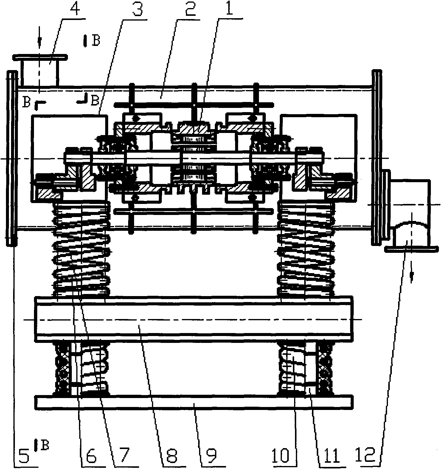
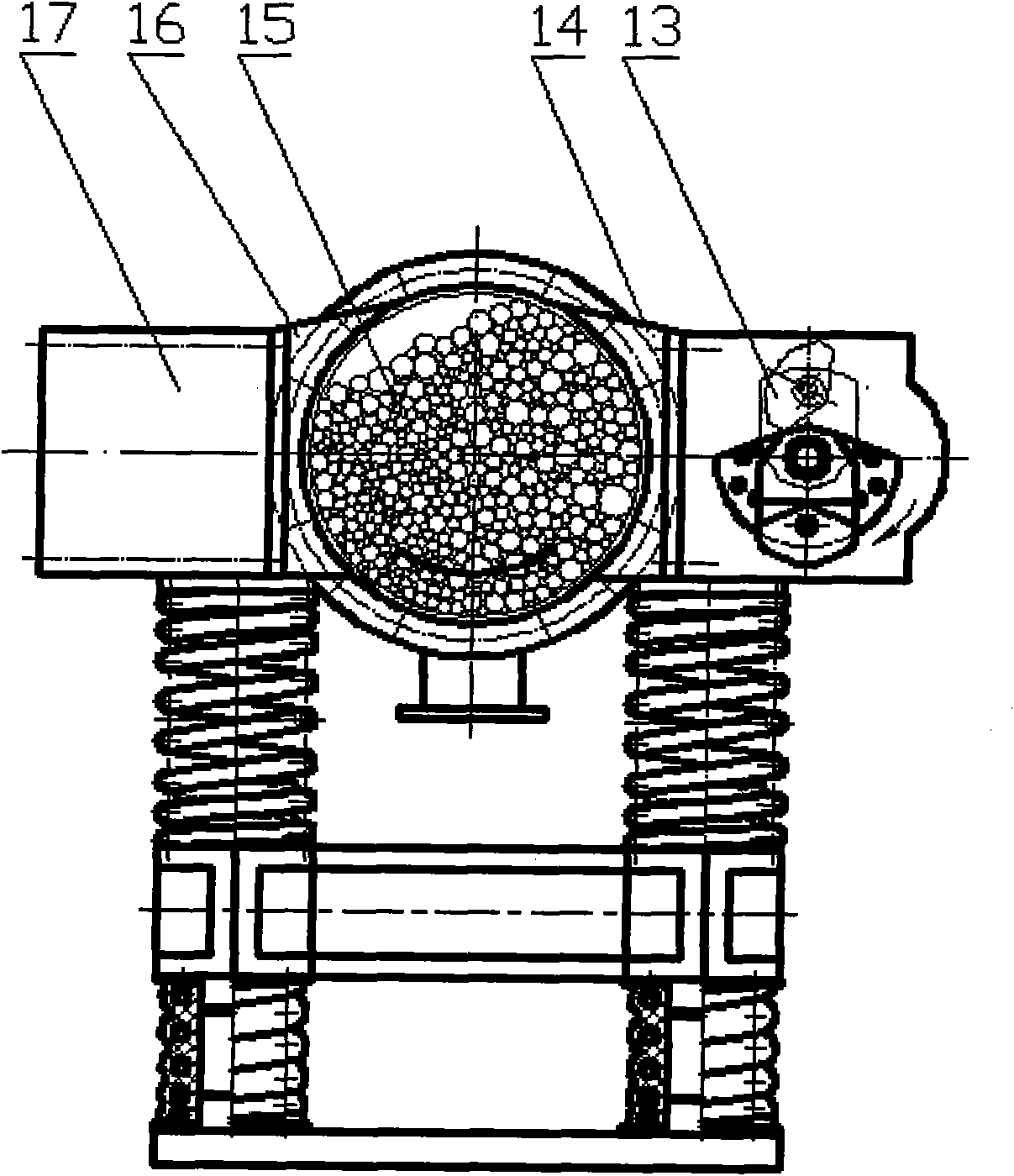
[0065] Refer to attached figure 1 -2, variable stiffness two-mass two-stage swing chaotic vibratory mill includes vibration motor 1, cylinder body 2, swing cover 3, feed port 4, end cover 5, main vibration spring guide column 6, main vibration spring 7, Lower body 8, base 9, vibration isolation spring 10, vibration isolation spring guide column 11, discharge port 12, swing assembly 13, right coupling frame 14, grinding medium 15, left coupling frame 16 and counterweight 17. Wherein the upper body comprises a vibration motor 1, a cylindrical body 2, a right coupling frame 14, a grinding medium 15, a left coupling frame 16 and a counterweight 17. There is at least one vibration motor 1 .

[0066] figure 1 In the structure represented by -2, the main vibration spring 7 can be a nonlinear variable stiffness helical metal-rubber composite spring, and the vibration isolation spring 10 can be a variable stiffness helical metal rubber composite spring. The springs 7 are connected, ...


PUM


Abstract

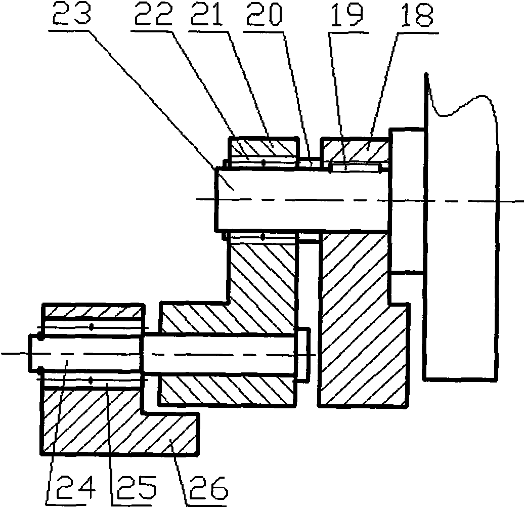
The invention discloses a variable stiffness double-mass secondary pendulum chaotic vibromill and relates to a vibromill, and in particular relates to a variable stiffness double-mass two-stage pendulum chaotic vibromill. The chaotic vibromill comprises an upper mass, a lower mass, a main vibration spring, a vibration isolation spring, a base, and the like, wherein the upper mass mainly comprises a vibration motor, a cylinder body, a right connecting frame, a left connecting frame and a counter weight; the cylinder body mainly comprises a feed inlet, an end cover, a discharge hole and a mill medium; the upper mass and the lower mass are connected through the main vibration spring, and the inner diameter of the main vibration spring is matched with the outer diameters of spring guide posts on the upper mass and the lower mass; the lower mass is supported on the base through the vibration isolation spring; the vibration motor comprises pendulum assemblies, and the pendulum assemblies are symmetrically distributed at the left end and the right end of a vibration motor shaft; and each pendulum assembly comprises a fixed pendulum, a flat key, a shaft sleeve, a primary movable pendulum, a bearing 1, a vibration motor shaft, a secondary movable pendulum shaft, a bearing 2 and a secondary movable pendulum.

Description

technical field [0001] The invention relates to a chaotic vibrating mill with variable stiffness two-mass body and two-stage pendulum, in particular to a chaotic vibrating mill with variable stiffness, two-mass body and two-stage pendulum, belonging to the technical field of vibration utilization engineering. Background technique [0002] Vibrating mill is a vibrating mechanical equipment that uses the principle of vibration to complete material crushing operations. Ordinary vibrating mills (including extra-large vibrating mills) mostly use linear helical springs and single-body structures, which are composed of one or more cylindrical containers supported on the springs. , the container rotates at its center of gravity or is biased on one side of the center of gravity by an ordinary vibrating motor (or vibrator) to vibrate unbalanced motion, and the grinding medium installed in the mill container collides with the material to be ground and Friction and crushing are the resu...

Claims


Application Information

Patent Timeline
IPC IPC(8): B02C17/14B02C17/18B02C17/24
Inventor 刘极峰杨小兰史金飞
Owner 江华瑶族自治县金牛开发建设有限公司
Learn More