Rolling mill work roll shifting device and safety bolt component thereof

A technology of safety bolts and work rolls, which is applied in the safety equipment of rolls, metal rolling stands, metal rolling mill stands, etc. The axial force cannot be unloaded, etc., to achieve the effect of simple structure, improved anti-rotation function, and equipment repair

Active Publication Date: 2012-12-26
MCC CAPITAL ENGINEERING & RESEARCH +1
View PDF0 Cites 0 Cited by
  • Summary
  • Abstract
  • Description
  • Claims
  • Application Information

AI Technical Summary

Problems solved by technology

If the axial force is transmitted to the transmission side of the rolling mill, it may damage the transmission system and have an adverse effect on the connecting shaft or the motor; if the axial force is transmitted to the operating side of the rolling mill, due to the limited stroke of the roll shifting hydraulic cylinder, When the stroke margin is used up, the axial force cannot be unloaded, so that the roll shifting device bears an excessive axial load, which may easily cause damage to the roll shifting device, and even lead to serious production accidents
When the roll shifting device breaks down, it is difficult to disassemble and assemble, and there are many devices that need to be disassembled, and the time for disassembly and installation is relatively long
[0009] 2. There are usually two pallet hydraulic drive devices in the existing roll shifting device, so the equipment cost is high, the piping structure is complicated, and the maintenance cost is high
[0010] 3. Since in the existing roll shifting device, the installation groove of the pallet is located on the center line LL' of the pallet, one end of the anti-rotation part of the existing roll shifting device is installed on the center line LL' of the pallet, The rotation arm of the anti-rotation part is shorter, so that the working section size of the anti-rotation part is increased

Method used


Image

  • Rolling mill work roll shifting device and safety bolt component thereof
  • Rolling mill work roll shifting device and safety bolt component thereof
  • Rolling mill work roll shifting device and safety bolt component thereof

Examples


Embodiment Construction

[0046] In order to have a clearer understanding of the technical features, purposes and effects of the present invention, the specific implementation manners of the present invention will now be described with reference to the accompanying drawings.

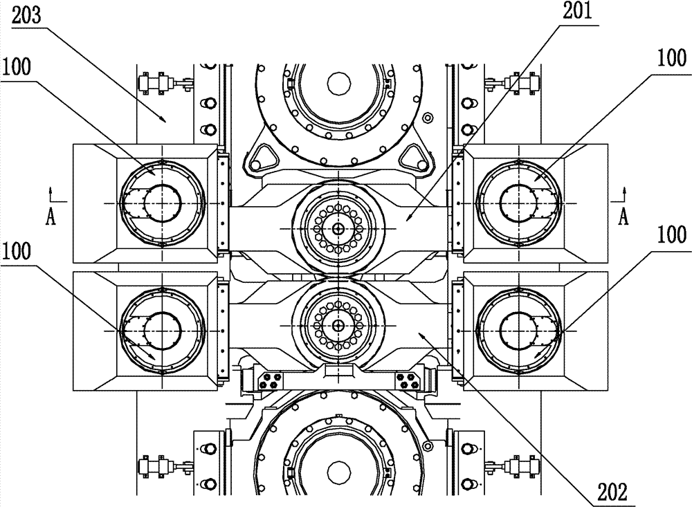
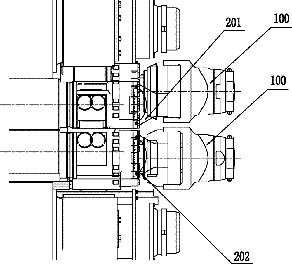
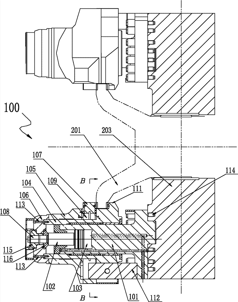
[0047] At least two work roll shifting devices of the rolling mill of the present invention are fixed symmetrically on both sides of the axis of the work roll of the rolling mill, on the frame on the operating side of the rolling mill, and connected with the wing-shaped ends of the work roll chocks. The roll shifting device of the present invention comprises: a roll shifting hydraulic cylinder, one end of the roll shifting hydraulic cylinder is fixed on the frame of the rolling mill, and a piston rod protrudes from the other end of the roll shifting hydraulic cylinder; Assembly, which can clamp the end of the bearing seat, the roll shifting moving assembly can be slidably set on the outer wall of the roll shifting hydraulic cylind...


PUM


Abstract

The invention discloses a rolling mill work roll shifting device, which comprises a shifting hydraulic cylinder and a shifting move component, wherein one end of the shifting hydraulic cylinder is fixed on a frame of a rolling mill; a piston rod extends out of the other end of the shifting hydraulic cylinder; the shifting move component can clamp the end part of a bearing block, and can slidingly sleeved on the outer wall of the shifting hydraulic cylinder; the piston rod is connected with the shifting move component through a detachable safety bolt component; and the safety bolt component is provided with at least one easy rupture part. When the axial force applied to the safety bolt component is larger than preset load, the easy rupture part is ruptured to release the axial force so as to protect the shifting device. The invention also provides a safety bolt component used for the rolling mill work roll shifting device.

Description

technical field [0001] The invention relates to a large-scale steel rolling equipment in the field of metallurgical machinery, in particular to a rolling mill work roll shifting device and a safety bolt assembly thereof. Background technique [0002] At present, various means and methods are used in the existing strip mills to improve the roll gap convexity and control the strip shape, among which the roll shifting technology is a widely used control method. In the existing rolling mill, there are upper work rolls and lower work rolls, one end of the upper and lower work rolls is installed in the frame (archway) window on the drive side of the rolling mill through the transmission side bearing seat, and the other end is installed through the operation side bearing seat. Installed in the frame window on the operating side of the rolling mill, the bearing seat on the operating side and the bearing seat on the driving side can move axially relative to the frame. On the operati...

Claims


Application Information

Patent Timeline
Patent Type & Authority Patents(China)
IPC IPC(8): B21B31/16B21B33/00
Inventor 任际军赵容仲张春光王颖江涛徐永华张俊伟刘延军李碧玲周雅婷张薇
Owner MCC CAPITAL ENGINEERING & RESEARCH
Why Eureka
Try Eureka