Building method of aluminum electrolysis cell

An aluminum electrolytic cell and masonry technology, which is applied in the field of aluminum electrolytic cell masonry, can solve problems such as uneven distribution of current density and magnetic field, poor electrolysis effect, and influence on current efficiency, and achieve uniform current density distribution and magnetic field distribution. Uniformity, the effect of reducing DC power consumption per ton of aluminum

Inactive Publication Date: 2011-01-19
SNTO TECH GRP
View PDF4 Cites 4 Cited by
  • Summary
  • Abstract
  • Description
  • Claims
  • Application Information

AI Technical Summary

Problems solved by technology

For example, Chinese patent CN2846445Y discloses a micro-slit bonded cathode carbon block structure for an aluminum electrolytic cell. The cathode carbon blocks are closely arranged and bonded by extrusion. The tank can enhance the anti-leakage ability of the cathode and improve the service life of the aluminum electrolytic cell, but its electrolysis effect is not good. The horizontal current in the aluminum liquid is very large during electrolysis, and the aluminum liquid fluctuates greatly and is unstable.
Another example is that the Chinese patent CN201416037Y discloses a new type of aluminum electrolytic cell. The aluminum electrolytic cell increases the distance between the cathode carbon blocks, and the height of the fastening material is lower than that of the cathode carbon blocks, so that grooves appear between the cathode carbon blocks. , its role is to reduce the voltage drop between electrodes and improve the efficiency of electric energy, but the uneven distribution of current density and magnetic field during the use of the electrolyzer seriously affects the current efficiency

Method used


Image

  • Building method of aluminum electrolysis cell
  • Building method of aluminum electrolysis cell
  • Building method of aluminum electrolysis cell

Examples


Embodiment 1

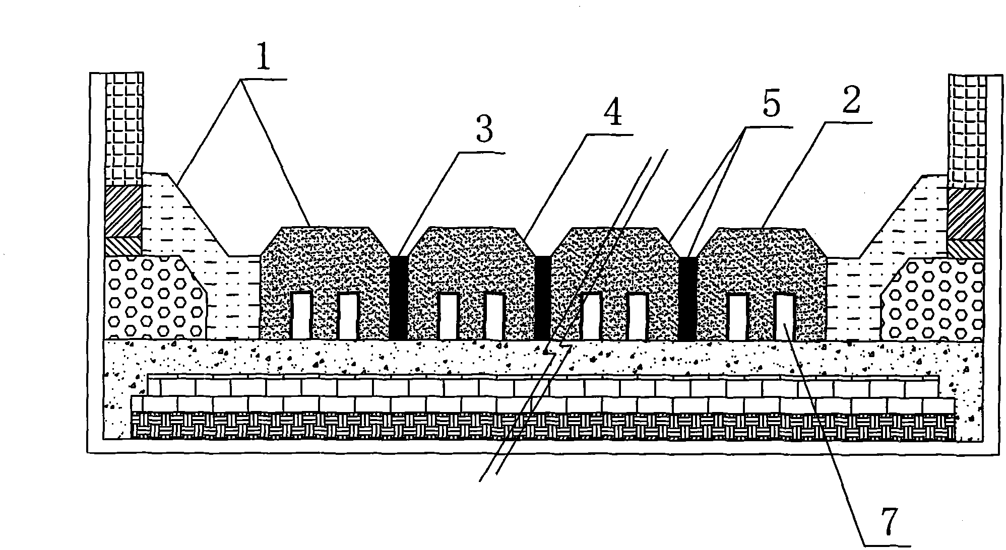
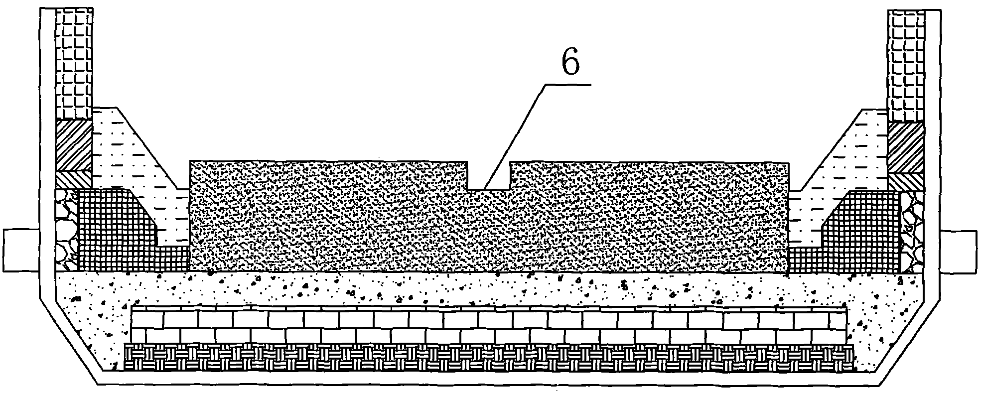
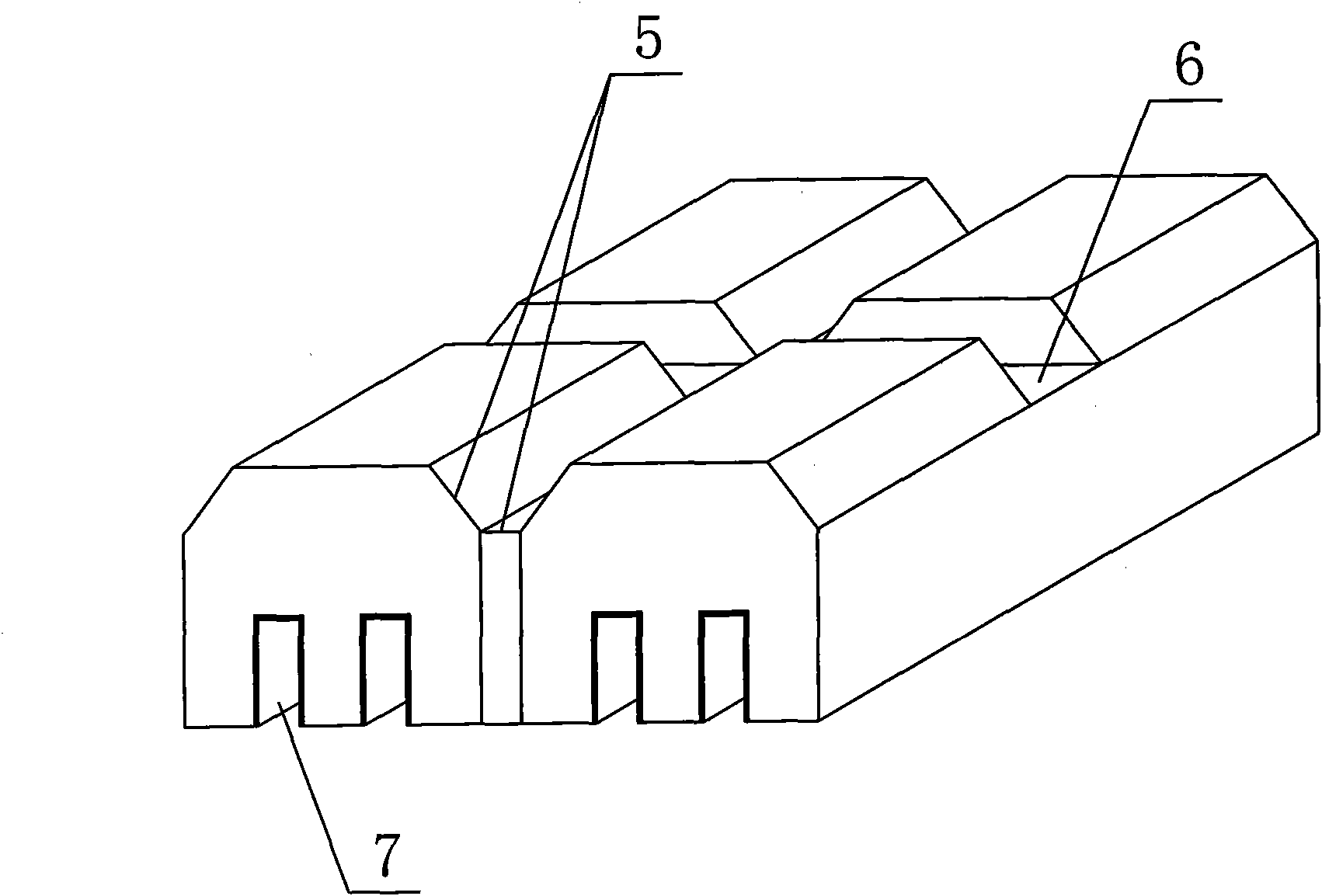
[0026] The masonry method of the aluminum electrolytic cell, in addition to the conventional masonry method, when making the cathode carbon block 2 of the electrolytic cell, perform symmetrical chamfering 4 on the upper end of the cathode carbon block 2 along the longitudinal direction, and open a transverse groove on the top of the cathode carbon block 2. Groove 6; when building cathode carbon blocks, there is a 20mm gap between adjacent cathode carbon blocks 2, and the gaps are tamped with cathode paste 3, and the relative chamfering 4 of adjacent cathode carbon blocks 2 is filled with the gap The cathode paste 3 forms a trapezoidal groove 5, and the depth of the trapezoidal groove 5 is the same as that of the transverse groove 6 at the top of the cathode carbon block 2; two longitudinal grooves 7 are provided at the bottom of the cathode carbon block 2, and the corresponding size is laid in the longitudinal groove 7. The steel rod, the cathode carbon block 2 and the steel ro...

Embodiment 2

[0028] The masonry method of the aluminum electrolytic cell, in addition to the conventional masonry method, when making the cathode carbon block 2 of the electrolytic cell, perform symmetrical chamfering 4 on the upper end of the cathode carbon block 2 along the longitudinal direction, and open a transverse groove on the top of the cathode carbon block 2. Groove 6; when building cathode carbon blocks, a 25mm gap is left between adjacent cathode carbon blocks 2, and the gaps are tamped with cathode paste 3, and the relative chamfering 4 of adjacent cathode carbon blocks 2 is filled with the gap The cathode paste 3 forms a trapezoidal groove 5, and the depth of the trapezoidal groove 5 is the same as that of the transverse groove 6 at the top of the cathode carbon block 2; two longitudinal grooves 7 are provided at the bottom of the cathode carbon block 2, and the corresponding size is laid in the longitudinal groove 7. The steel rod, the cathode carbon block 2 and the steel rod...

Embodiment 3

[0030]The masonry method of the aluminum electrolytic cell, in addition to the conventional masonry method, when making the cathode carbon block 2 of the electrolytic cell, perform symmetrical chamfering 4 on the upper end of the cathode carbon block 2 along the longitudinal direction, and open a transverse groove on the top of the cathode carbon block 2. Groove 6; when building cathode carbon blocks, there is a 30mm gap between adjacent cathode carbon blocks 2, and the gaps are tamped with cathode paste 3, and the relative chamfering 4 of adjacent cathode carbon blocks 2 is filled with the gap The cathode paste 3 constitutes a trapezoidal groove 5, and the depth of the trapezoidal groove 5 is the same as that of the transverse groove 6 at the top of the cathode carbon block 2; a longitudinal groove 7 is opened at the bottom of the cathode carbon block 2, and steel of corresponding size is laid in the longitudinal groove 7. The cathode carbon block 2 and the steel rod are tampe...


PUM


Abstract

The invention relates to a building method of an aluminum electrolysis cell, which comprises a conventional building method and comprises the following building steps: (1) when cathode blocks of the electrolysis cell are manufactured, symmetrically chamfering the upper end part of each cathode block along the longitudinal direction, and forming a transverse groove at the top of each cathode block; (2) when the cathode blocks are built, reserving a gap of 20-40mm between every two adjacent cathode blocks, and tamping the gap by cathode tamping paste, wherein the opposite chamfers of the adjacent cathode blocks and the cathode tamping paste filled into the gap form a trapezoidal groove, and the depth of the trapezoidal groove is the same as the depth of the transverse groove at the top of each cathode block; and (3) forming one or two longitudinal grooves at the bottom of each cathode block, laying steel bars of corresponding sizes in each longitudinal groove, and tamping the gap between each cathode block and each steel bar by cathode steel bar paste. The aluminum electrolysis cell built by the method can greatly reduce the horizontal current in aluminum liquid to enable the current density of the cathode blocks and the cathode steel bars to be more uniform, thereby greatly prolonging the service life of the electrolysis cell.

Description

1. Technical field [0001] The invention relates to a method for building an aluminum electrolytic cell, in particular to a method for building an aluminum electrolytic cell with a special-shaped cathode structure. 2. Background technology [0002] At present, the extraction of aluminum in industry is mainly produced by cryolite-alumina molten salt electrolysis, and its special equipment is an electrolytic cell lined with carbonaceous materials. It is a refractory material and insulation brick. The carbon lining of the electrolytic cell is generally made of carbon bricks made of anthracite or graphite materials or a mixture of the two, which have good resistance to sodium salt and electrolyte corrosion. The carbon paste made of carbonaceous material is used for tamping between the block and the carbon block. [0003] The cathode structure of the existing aluminum electrolytic cell mostly adopts a groove at the bottom of the cathode carbon block and is equipped with a cathode...

Claims


Application Information

Patent Timeline
Patent Type & Authority Applications(China)
IPC IPC(8): C25C3/08
Inventor 邓发权龚克成敬叶灵
Owner SNTO TECH GRP
Why Eureka
Try Eureka